Phoenix LT4 Lane Machine Operation, Maintenance, and Parts Manual
3-16 Rev. Date: 01/22 61-900040-000
3.4 THE HANDLE
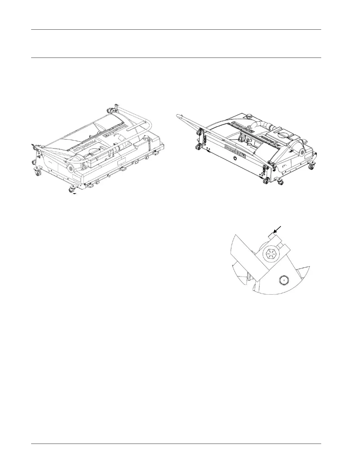
The handle, shown in Figure 3- 32 and Figure 3- 33, can be placed in any position from flat
against the Phoenix LT4 housing to fully rearward and parallel with the floor. This allows
the handle to be put in whatever position is comfortable for the user when operating,
moving, or storing the Phoenix LT4.
The handle is equipped with adjustable friction hinges
which allow it to remain in any position and not fall from its
own weight. They also aid in the maneuverability of the
machine in the operating position. If the handle is too
difficult to pivot or pivots too freely, adjust the socket head
hex screws, as shown in Figure 3- 34, at each handle pivot
until the proper resistance is obtained. Refer to Section
4.3.8 – Adjusting the Handle Hinges for more information
on adjusting the friction hinges.
SUGGESTION
Before releasing the handle when the Phoenix LT4 starts to move down the lane, it
is strongly recommended that it be lowered as the machine is released. This
ensures the handle will not contact the underside of the masking unit or pinspotter.
The handle has a START button and hook-and-loop straps. The Start button, which is
shown in Figure 3- 35 on the next page, starts the operation of the machine, performing the
functions of the selected program. When the start button is pressed the first time, the
vacuum head will drop, the vacuum motor will start, and cleaner will start being sprayed
onto the lane. For safety, the drive motor will not engage until the Start button has been
pressed a second time within 5 seconds of the first push. If 5 seconds passes between the
1
st
press and the 2
nd
press, the 1
st
press of the start button must be done again.