Operation
61-900040-000 Rev. Date: 01/22 3-19
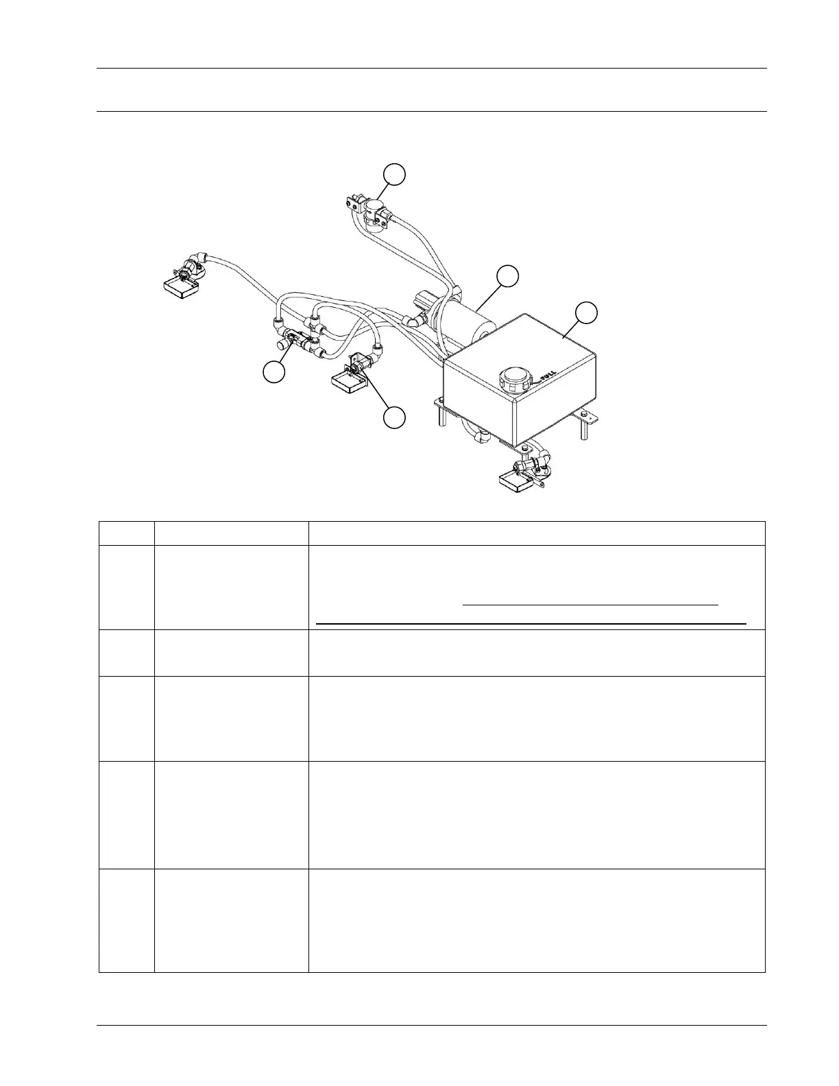
3.6 CLEANING OPERATION COMPONENTS
The components used in the cleaning operation are shown in Figure 3- 38, Figure 3- 39,
and Figure 3- 40 described below in Table 3- 4, Table 3- 5, and Table 3- 6, respectively.
Table 3- 4
This tank holds the cleaning solution. It holds enough to
clean approximately 16 lanes. When placing the machine in
the storage position, ensure the cleaner level is below the
level of the cap or cleaner could drip from the cap’s vent hole.
This pump transfers cleaner from the cleaner tank to the
spray head.
Located on the rear of the waste tank mounting bracket
in the tubing running from the cleaner tank to the cleaner
pump, the filter is designed to strain out any particles that
could lodge in the pump or spray nozzles.
The spray heads distribute the cleaner on the lane and
can be adjusted for both amount of spray, and direction.
Refer to Section 4.3.4 – Adjusting the Cleaner Spray for
instructions on clearing clogs and how to change the
amount of cleaner dispensed from the spray heads.
Cleaner Flow
Control Valve
This manually operated valve is used to control the
amount of cleaner being supplied to the spray heads.
Throttling (closing) the valve increases cleaner flow to
the spray heads. Excess cleaner is routed back to the
cleaner tank.