Phoenix LT4 Lane Machine Operation, Maintenance, and Parts Manual
4-20 Rev. Date: 01/22 61-900040-000
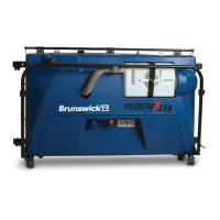
1. Unlatch the oil compartment door latches,
disconnect the vacuum hose and remove the
waste tank, remove the cap from the cleaner
tank, remove the two screws from each side of
the hood as shown in Figure 4- 211, and lift the
hood from the frame. Set the screws aside.
2. Disassemble the spray nozzle by unscrewing the
nozzle tip from the nozzle body as shown in Figure 4- 222 (some components are
hidden to allow for a more detailed view).
3. Soak the spray nozzle and strainer check valve in warm water for several minutes
then blow air through the end of each.
4. Reassemble the strainer check valve, spray nozzle, and nozzle tip retainer then
screw them onto the nozzle body. Before tightening, ensure the spray nozzle is
positioned to deposit cleaner spray in the desired direction.
5. Reinstall the hood, cleaner tank cap, waste tank, and vacuum hose.
4.3.5 Adjusting the Vacuum Head Height
The vacuum head linkage is designed to allow the vacuum head to float on the lane so that
it maintains its cleaning efficiency over the bumps and dips that can form on a lane’s
surface over time. Correct adjustment of the vacuum head is important. The agitator and
squeegee should be well clear of the lane when the vacuum head is retracted while
allowing the agitator and squeegee to contact the lane with the correct amount of deflection
when extended. If the vacuum head is too high, puddles of cleaner can be left on the lane.
If the vacuum head is too low, a hazy film can be left on the lane.
When the machine is turned on, the vacuum head solenoids energize to pull the vacuum
head up away from the lane. During a cleaning operation, the solenoids de-energize to