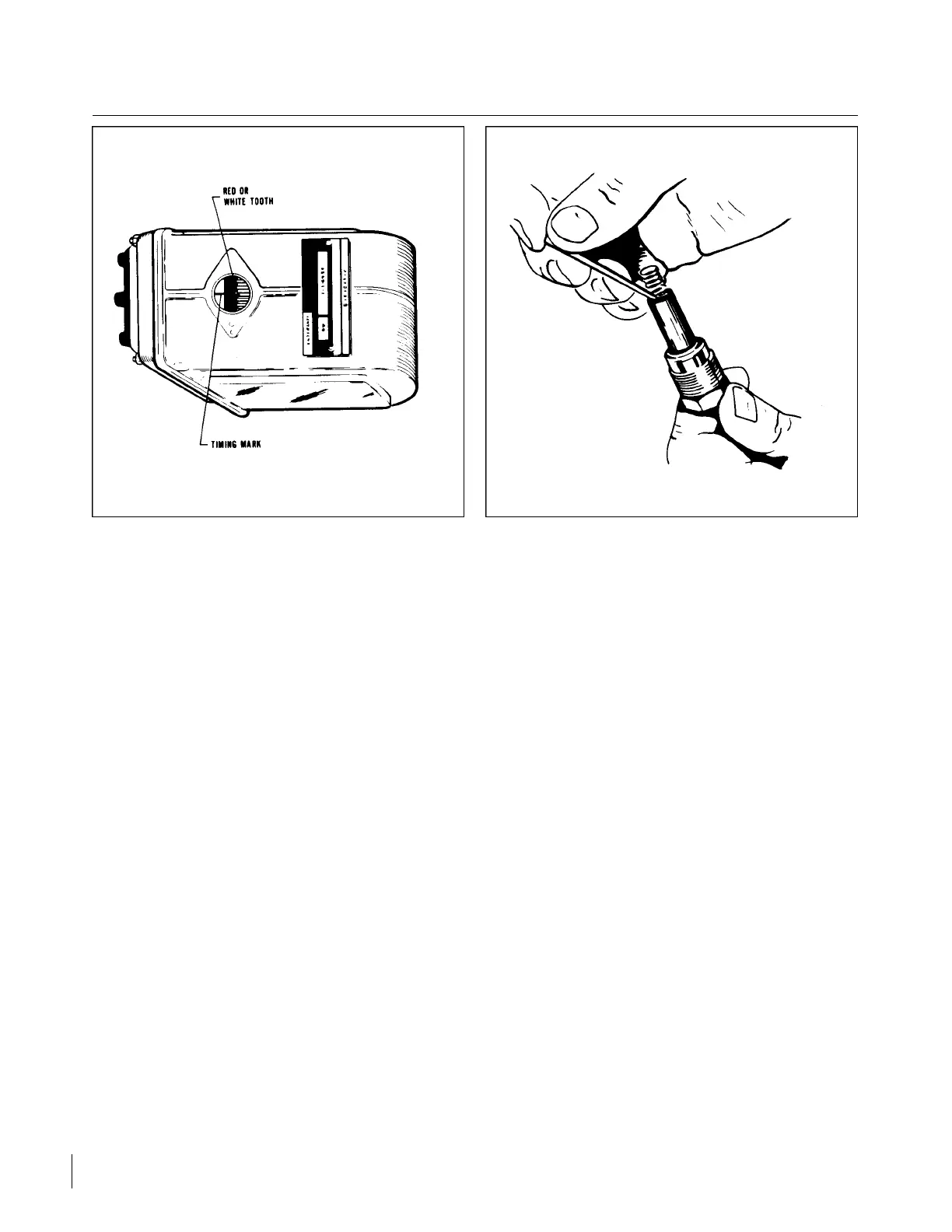
Figure 8A-15. Magneto Timing Marks Figure 8A-16. Removing Spring From Lead
Assembly
d. After both magnetos have been timed, check, as described below, to ascertain that both magnetos are
set to fire together.
e. Back off the crankshaft a few degrees; the timing lights should go out. Bring the crankshaft slowly
back in direction of normal rotation until the timing mark and the hole in the starter housing are in
alignment. At this point, both lights should go on simultaneously. Tighten nuts to specified torque.
f. After magnetos have been properly timed, replace breaker cover and secure.
g. Install the ground lead and the retard spark lead on the left magneto.
h. Place the harness terminal plate on the magneto and tighten nut around the plate alternately to seat
cover squarely on magneto. Torque nuts to 18 to 22 inch-pounds.
8A-31. HARNESS ASSEMBLY.
8A-32. INSPECTION OF HARNESS.
a. Check lead assemblies for nicks, cuts, mutilated braiding, badly worn section or any other evidence of
physical damage. Inspect spark plug sleeves for chafing or tears and damaged or stripped threads on
coupling nuts. Check compression spring to see if it is broken or distorted. Inspect grommet for tears.
Check all mounting brackets and clamps to see that they are secure and not cracked.
b. Using an ohmmeter, buzzer, or other suitable low voltage device, check each lead for continuity. If
continuity does not exist, wire is broken and must be replaced.
c. For electrical test of harness assembly, use a high voltage, direct current tester such as the TA K K
Model 86 or 86A or an equivalent direct current high voltage tester capable of delivering a test
potential of 10,000-volts. Connect ground lead to high voltage tester to outer shielding braid of a
single lead. Connect plug terminal. Turn tester “ON” and apply 10,000-volts. The insulation resistance
should be 100 megohms minimum. Proceed to check other leads of harness in same manner.
d. Minor repair of the harness assembly, such as replacement of contact springs, spring retainer
assemblies, insulating sleeves or of one lead assembly, can be accomplished with the harness assembly
mounted on the engine. However, should repair require replacement of more than one lead assembly or
of a cable outlet plate, the harness should be removed from the engine and sent to an overhaul shop.
Revised: 8/31/77
2D18
CHEROKEE ARROW III SERVICE MANUAL
POWER PLANT - LYCOMING