USER MANUAL
Page 14 of 86 URM18PH392 Rev A. May 2020
1.2 VIPER™ SYSTEM COMPONENTS
The VIPER™ System consists of a System Electronic Unit (SEU), one to sixteen Sensors and one to four
electromagnetic (EM) Sources. Communication with the system is via USB 2.0 or RS-422. The system only
requires 5 volt power. Host computer apps, programming libraries, and documentation are installed via web
download or thumb drive.
VIPER™ SEU 1.2.1
The VIPER™ SEU comes in three variations:
The VIPER™ 4 system supports one EM Source and up to four Sensors.
The VIPER™ 8 system supports up to two EM Sources and up to eight Sensors.
The VIPER™ 16 system supports up to four EM Sources and up to sixteen Sensors.
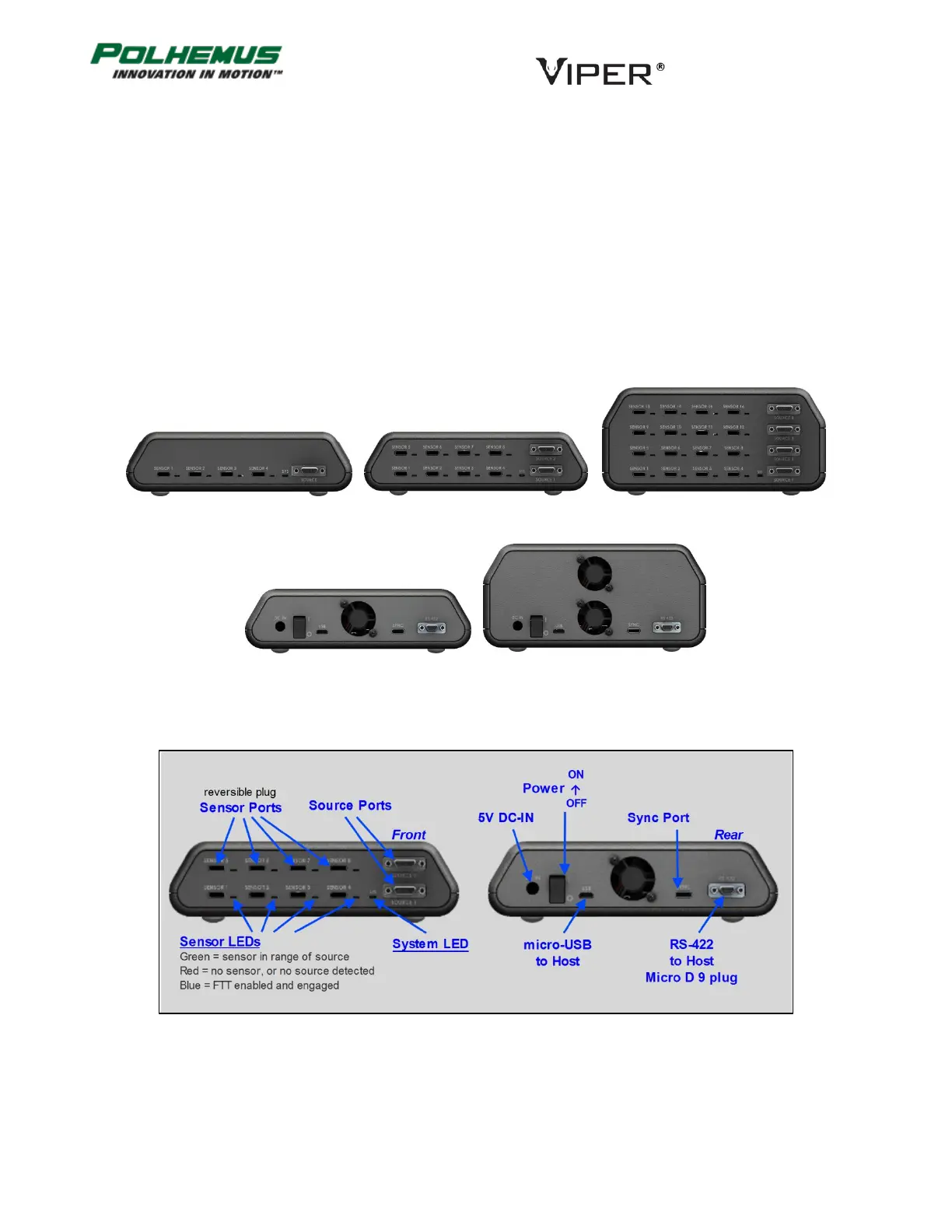
Figure 3 below identifies controls and ports on a VIPER™ 8 chassis.
Figure 4 below details approximate VIPER™ SEU dimensions. Note that all SEUs have the same footprint. Rubber
feet add approximately 0.2 inches (0.51 cm) to the height.
FIGURE 1. VIPER™ SEU FRONT VIEW: VIPER™ 4, VIPER™ 8, VIPER™ 16
FIGURE 2. VIPER™ SEU REAR VIEW: VIPER™ 4/8, VIPER™ 16
FIGURE 3. VIPER™ 8 SEU PANEL LEGEND