USER MANUAL
Page 20 of 86 URM18PH392 Rev A. May 2020
FTT® should start with the Sensor in “Home” location and with the FT-Sensor’s
SEU Sensor port in a GREEN LED state. The Sensor port LED will alternate
GREEN and BLUE until Sensor is “Homed” this way.
At introduction, VIPER™ FTT® has two modes of operation: Stationary Source Mode for conventional tracking
applications where VIPER™ Sources are mounted in a fixed position and Moving Source Mode where VIPER™
Sources may be used in innovative dynamic and diverse scenarios. Be sure to understand the difference
between the modes and select the best one for your tracking applications. Refer to Section 4.2.12 FTT MODE
command for details about the available FTT® modes.
Both FTT® modes will “carry” the high-quality tracking performance of the VIPER™ tracker in difficult conditions
for a period of time but due to the iterative nature of the filter, it is necessary to periodically return the FT Sensor
to Home in order to effectively reset the tracker’s measurement quality factors.
FTT® is a real-time distortion mitigation correction.
Due to the iterative nature of this feature, FTT® can cause tracking output to
be less precise in magnetically benign tracking environments than without it.
FTT® is a solution to a problem, but if no problem is present, it may be best
not to engage at all so that tracking solution variables are minimized. Users
may decide to leave FTT® Mode OFF in many situations depending upon
tracking quality needs.
2.2 I/O CONSIDERATIONS
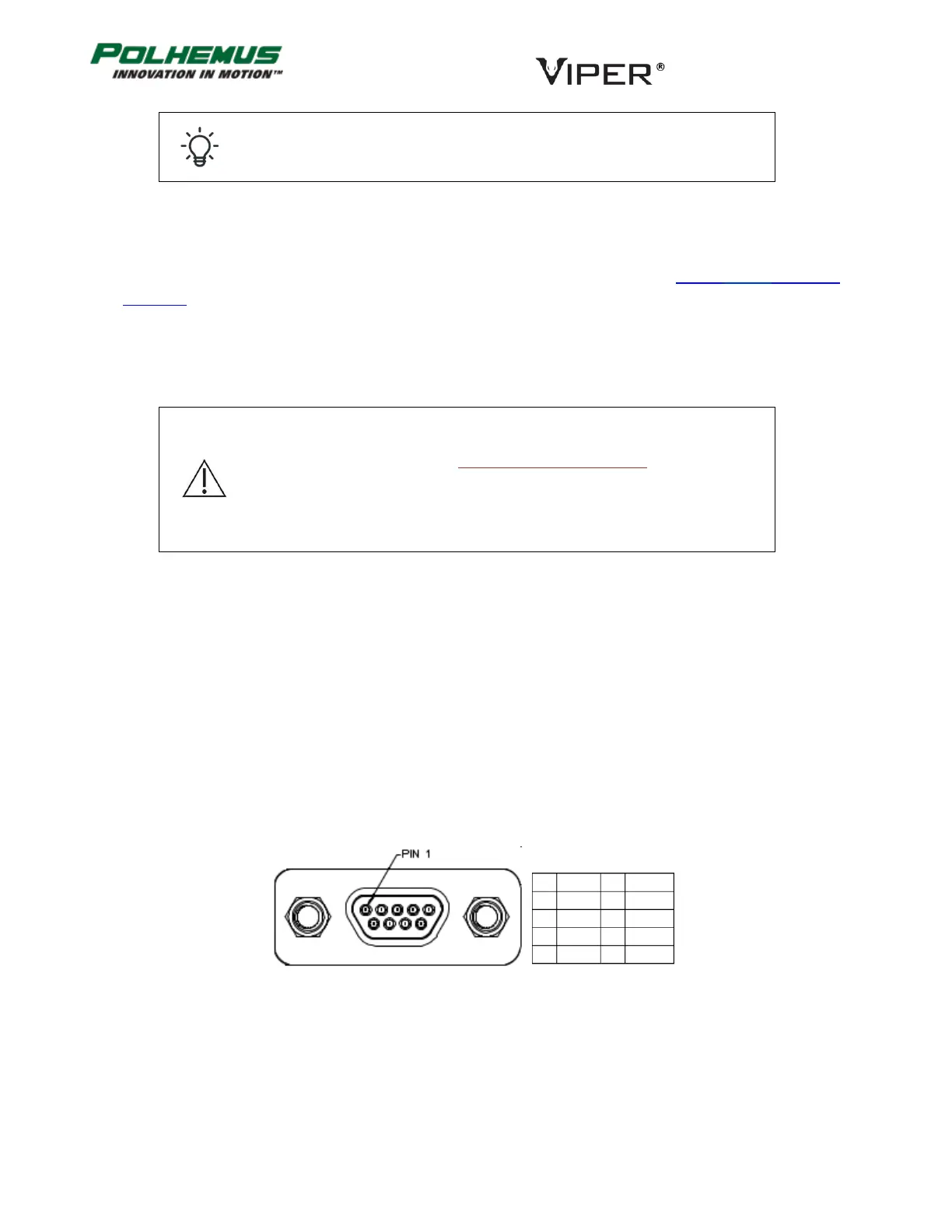
VIPER™ has two communication I/O ports: USB and RS-422. The USB port uses a micro USB connector. The RS-
422 port uses a Micro D 9-pin plug connector (male, Molex part number 836119006). The pinout is shown in
Figure 8 below.
Either I/O port can be used for command input and data output. When the VIPER™ is powered ON, either port
will respond to commands when used as a single output port.
VIPER™ also supports a dual-output mode where the tracker data stream is output to both ports. In this mode, it
is recommended that the USB port be used for command input (as well as data output) and the RS-422 port be
monitored only for output data.
FIGURE 8. PINOUT VIPER™ RS-422 MALE CONNECTOR
Micro D 9-pin Plug, Molex part 83611-9006