USER MANUAL
Page 48 of 86 URM18PH392 Rev A. May 2020
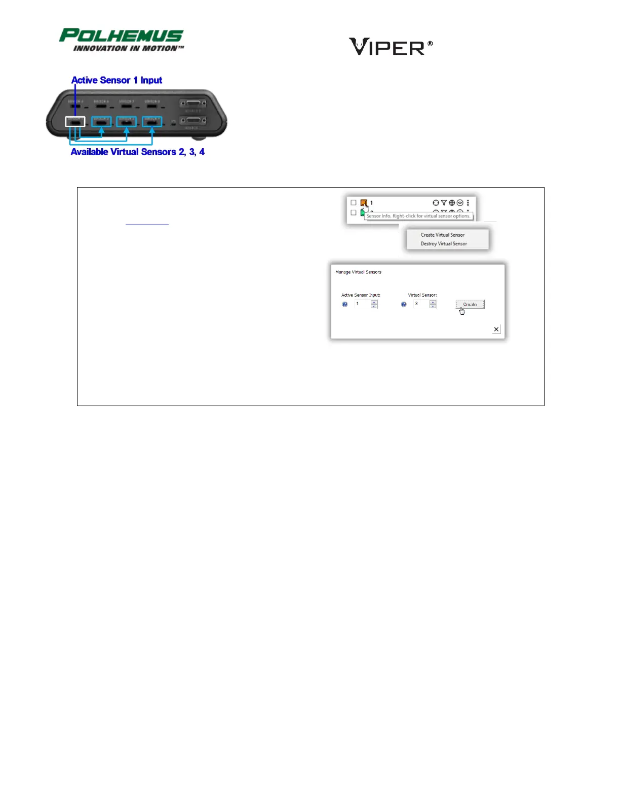
For example, if a live Sensor 1 is connected, Virtual Sensors 2, 3, and 4
could be created using Sensor 1 as the Active Sensor Input. (Figure 21)
Note that a live Sensor may be used as Input to “feed” multiple Virtual
Sensors at the same time.
In VIPER™ Command Manager, to create or
destroy a virtual Sensor, right-click on a Sensor
icon in the Edit Mode Status Pane.
FIGURE 21. VIRTUAL SENSOR EXAMPLE