USER MANUAL
URM18PH392 Rev A. May 2020 Page 75 of 86
APPENDIX B. SOURCE HEMISPHERES
If the application requires the Sensor(s) to move back and forth to different sides of
the Source, Hemisphere Tracking or Auto-Hemisphere must be enabled with the
HEMISPHERE command.
When the VIPER™ system is started, Sensors track by detecting the presence of the electromagnetic (EM)
field produced by one or more Sources in the tracking area.
The field emitted by the Source is a symmetrical dipole field. That means that when it is detected from
any direction, the detected field is identical to the field emitted in the opposite direction. For that reason,
the VIPER™ Sensor cannot initially distinguish the direction from which it initially detects the Source; it
needs to be told at startup, using the HEMISPHERE command or via Auto-Hemisphere.
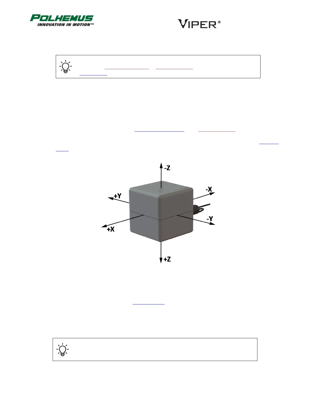
Source hemispheres are described by the Cartesian axes with origin at the center of the Source. Figure 22
below depicts the location of the +/- X, Y, Z sides of the standard Source.
Unless configured otherwise, VIPER™ assumes that all Sensors will detect the Source(s) from the +X direction.
That is, the Sensors are assumed to operate in the “plus X” hemisphere. The default hemisphere setting is +X
for all Sensors. It is for this reason that the Getting Started section advises the novice user to position the Sensor
on the +X side of the Source.
When the correct hemisphere is not established, the Sensors’ position coordinates output will frequently have
the wrong sign.
Incorrect hemisphere setting or operation is the number one cause of sign errors in
the position data.
FIGURE 22. SOURCE HEMISPHERES