USER MANUAL
URM18PH392 Rev A. May 2020 Page 31 of 86
3.5 CONFIGURING VIPER™ MULTI-SOURCE MODES OF OPERATION
As described previously in Section 2. , VIPER™ is able to drive up to four Source components.
Note: When multiple Sources are used, each Source must operate at a
different electromagnetic (EM) frequency.
If multiple Sources of the same frequency are connected, VIPER™ will not
operate.
Polhemus offers Sources in a variety of EM frequencies.
When VIPER™ powers up, it detects plugged in Sensor and Source components. (Hot swapped Sensors are also
detected when plugged in while VIPER™ is running.)
Depending on the pattern of connected Sources, VIPER™ defaults to one of several standard modes of operation.
These modes are detailed in the following Sections 3.5.1, 3.5.2, and 3.5.3.
Each mode is characterized by:
Which Source(s) the Sensor detects for determining position and orientation (P&O)
and
Which Source is the referenced Cartesian origin (0, 0, 0) and null orientation.
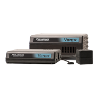
SINGLE-SOURCE MODE 3.5.1
Applies to VIPER™ 8 and VIPER™ 16 systems.
One Source is plugged into Source port 1.
All Sensors report P&O relative to Source 1.
No Source is plugged into any other Source port.
DUAL-SOURCE MODE 3.5.2
Each group of 8 Sensors report P&O with respect to Sources 1 and 3. In this mode, VIPER™ behaves as two
independent 8-Sensor tracking systems.
Applies to VIPER™ 16 systems only.
Two Sources are plugged into Source ports 1 and 3.
Sensors 1-8 report P&O relative to Source 1.
Sensors 9-16 report P&O relative to Source 3.
Sources 1 and 3 must operate at different EM frequencies*.
No Source is plugged into Source ports 2 and 4.
*See warning note above.
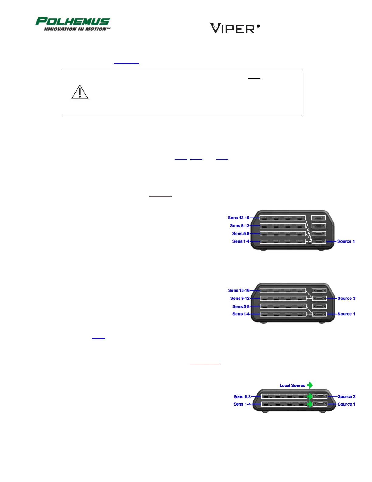
LOCAL-SOURCE MODE 3.5.3
Each group of 4 Sensors report P&O with respect to the Local Source. Refer to Figure 15 and Figure 16 below to
see the location of Local Sources.
Applies to all VIPER™ systems; this is the standard operating mode for VIPER™ 4.
On a VIPER™ 8 system:
Behaves as two independent 4-Sensor systems.
Two Sources are plugged in to Source ports 1 and 2.
Sources 1 and 2 must operate at different EM frequencies*.
Sensors 1-4 report P&O with respect to their Local Source: Source 1.
Sensors 5-8 report P&O with respect to their Local Source: Source 2.
FIGURE 13. VIPER™ 16 SINGLE-SOURCE MODE
FIGURE 14. VIPER™ 16 DUAL-SOURCE MODE
FIGURE 15. VIPER™ 8 LOCAL SOURCE LOCATIONS