USER MANUAL
URM18PH392 Rev A. May 2020 Page 43 of 86
Further, each Sensor can operate correctly on only one side of a Source, unless Hemisphere Tracking is used.
With Hemisphere Tracking enabled, VIPER™ continuously modifies the operating hemisphere, allowing full
tracking coverage around all sides of the Source.
Note: To start Hemisphere Tracking, VIPER™ must be operating in a known,
valid hemisphere. That is, the Sensor must be located in the currently
configured hemisphere of operation.
Note: Hemisphere Tracking is automatically enabled with Auto-Hemisphere
detection.
For Expanded Tracking Area Multi-Source configurations (Section 3.5.5), Startup Hemisphere is configured with
the SOURCE CONFIGURATION setting (Section 4.2.7).
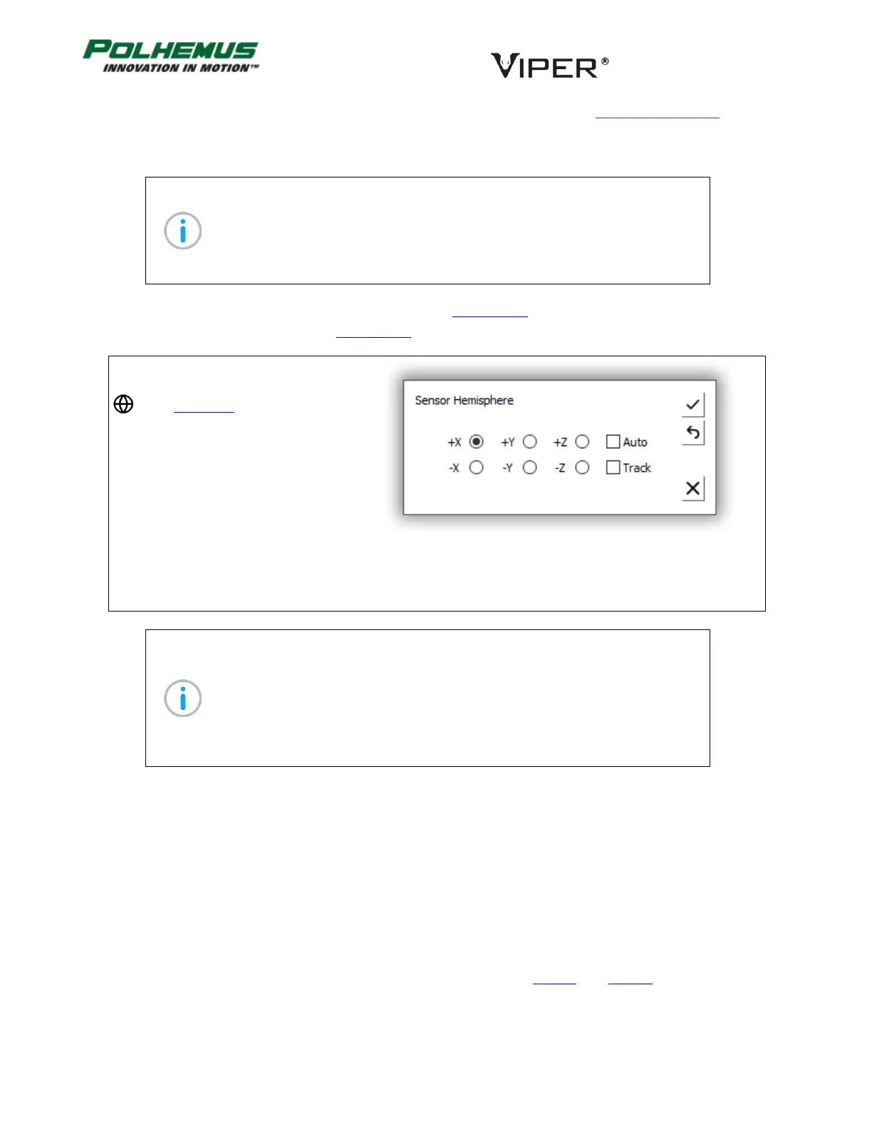
In VIPER™ Command Manager,
Hemisphere is configured by selecting
in the Edit Mode Status Pane.
Default: +X for all Sensors
Persistent: YES, except Hemisphere Tracking, unless Auto-Hemisphere is enabled.
Note: If Auto-Hemisphere is applied to a non-FT Sensor, VIPER™ responds to the
HEMISPHERE command with a warning, and Auto-Hemisphere is not engaged
on that sensor. Instead, Hemisphere Tracking is enabled on that Sensor and the
+X Hemisphere is assumed.
If the Auto-Hemisphere was previously enabled and the detected Sensor is not
an FT Sensor, the default Hemisphere Tracking will be enabled and +X starting
Hemisphere will be assumed.
FILTER COMMAND 4.2.10
VIPER™ employs optional filtering that is designed to control noise (jitter) in the P&O data output. Filters can be
applied to position or orientation or both. The FILTER command is applied on a per-Sensor basis.
Traditional Polhemus Adaptive Filter
The FILTER command establishes the sensitivity, boundary, and transition control parameters for the Traditional
adaptive filter that operates on the position and orientation outputs of the VIPER™ system. The user can adjust
the parameters of this filter to fine-tune the overall dynamic response of VIPER™ or select pre-configured
presets. The definitions of these parameters and presets are detailed in Table G. and Table H. below.