USER MANUAL
Page 16 of 86 URM18PH392 Rev A. May 2020
SENSOR 1.2.2
Position and Orientation (P&O) is calculated at the EM center of the Sensor device, relative to a Cartesian origin
location in the motion tracking area. By default, this reference location is at the EM center of a VIPER™ Source,
so all calculated Sensor P&O is relative to that Source. Alternatively, the reference location may be defined by
the user, selected for the specific needs of the application. Refer to Sections 3.5 “Configuring VIPER™ multi-
source modes of operation“ and 4.2.14 “SOURCE CONFIGURATIONS AND MODES OF OPERATION“ for details
about this.
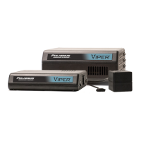
The VIPER™ Sensor is available in multiple styles, including:
FT-Standard: with mounting holes
FT-Flatsided: without mounting holes
FT-Clip: with tapered edges that fit into a mounting clip
The Sensors connect easily to the SEU via reversible plugs so the orientation of the connector does not matter
when plugging in.
See Appendix C for Sensor dimensions.
FIGURE 5. VIPER™ SENSORS. FROM TOP: FT-STANDARD, FT-FLATSIDED, AND FT-CLIP (WITH CLIP SHOWN)