USER MANUAL
Page 56 of 86 URM18PH392 Rev A. May 2020
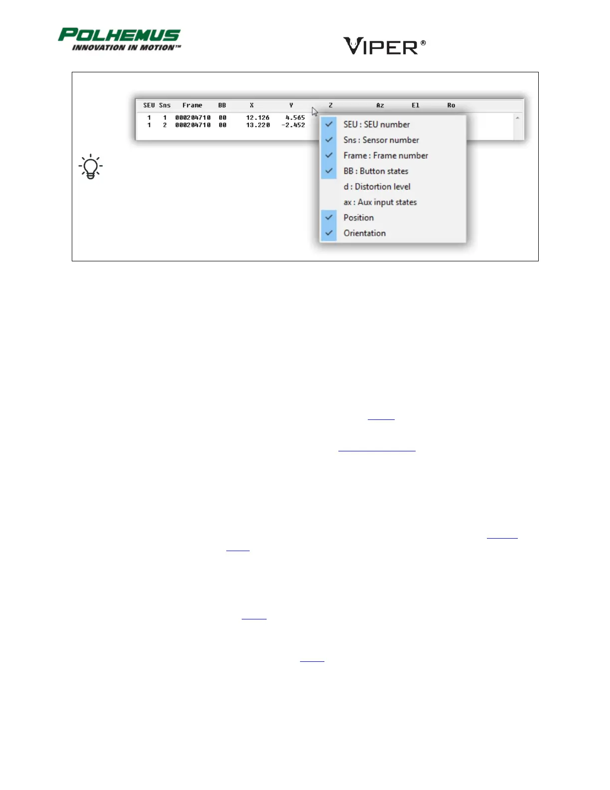
Right-click the mouse over the title bar in the text pane to select data to be displayed.
ALTERNATIVE P&O FRAME WITH ACCELERATION 4.4.2
VIPER™ has the ability to output P&O in an alternative data mode that includes Sensor acceleration in X, Y, Z axes
and magnitude.
A VIPER™ P&O frame with acceleration data contains the fields below. VIPER™ Command Manager displays the
fields identified with * by default. The other fields are available for display by configuring the P&O display
parameters.
SEU ID ..................................................
32-bit SEU identifier configured by SEU ID command.
SEU Frame number .............................
32-bit number of frames tracked since the SEU was powered on, or since
frame count was reset. See Frame Count Reset
above.
Sensor count .......................................
32-bit number of Sensors’ P&O data that is contained in the frame.
For each reporting Sensor:
Sensor number ...............................
7-bit numeric reflecting the SEU Sensor port that the Sensor is plugged into.
Sensor button states.......................
2-bit states of any button switches integrated into the Sensor. A VIPER™
Stylus uses one of these bits.
Distortion level ...............................
8-bit numeric distortion level detected by the Sensor in levels 0-255.
Auxiliary digital input value ...........
10-bits of available data input for custom integrated hardware.
Sensor Position (X, Y, Z) .................
32-bit floating point Cartesian coordinates in position units configured by
the UNITS command.
Sensor Orientation .........................
Expressed as (3) or (4) 16-bit compressed values for Euler Angles (Azimuth,
Elevation, Roll) or a 4-term Orientation Quaternion Q(w, x, y, z)*, as
configured by the UNITS command.
[*Note order of Quaternion components: Scalar value w is output first.]
Sensor Acceleration ........................
Expressed as (4) 16-bit compressed values for acceleration in X, Y, Z and
magnitude.