USER MANUAL
URM18PH392 Rev A. May 2020 Page 47 of 86
Moving Source Mode: This mode is for dynamic configurations that involve VIPER™ Sources that do move in 3D
space during tracking. Moving Source Mode is useful in diverse applications such as:
a small size TX1 Source embedded in an ultrasound wand that moves while in use, or
a Source installed within a motion platform simulator, or
a Source installed in a moving vehicle.
Note: Moving Source Mode is only applicable to systems operating in Local
Source Mode, where Sensors report P&O relative to their Local Source. To learn
more about Local Source Mode, see Section 3.5.3.
In VIPER™ Command Manager, FTT® mode is
configured by selecting in the Edit Mode
Status Pane.
FTT® Stationary Source Mode can be enabled and
disabled for all Sensors by typing q.
Default: OFF for all Sensors
Note: If FTT® Mode is applied to a non-FT Sensor, VIPER™ responds to the FTT
MODE command with a warning, and FTT® Mode is OFF on that sensor.
If the FTT® Mode was previously enabled and the detected Sensor is not an FT
Sensor, FTT® Mode will be OFF on that detected Sensor.
VIRTUAL SENSOR COMMAND 4.2.13
This command is used to create or destroy a Virtual Sensor with an unused Sensor number. VIPER™ outputs
P&O for a Virtual Sensor from a configured Input, which is selected from available connected live (active)
Sensors. Once created, a Virtual Sensor may be configured just like an active Sensor—this is useful for testing,
comparing and troubleshooting behavior produced by Sensor
configuration settings.
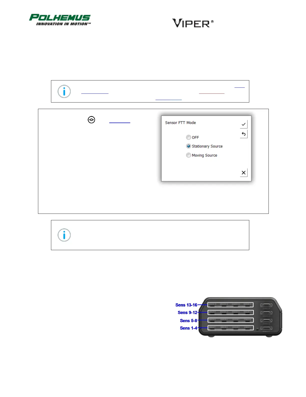
When creating a Virtual Sensor, the Virtual Sensor’s number is
chosen from unused sensor numbers local to the active Sensor
Input. Local sensor numbers are in groups of 4 on the VIPER™
panel as depicted in Figure 20.
FIGURE 20. LOCAL SENSOR GROUPS