USER MANUAL
URM18PH392 Rev A. May 2020 Page 23 of 86
3. GETTING STARTED
3.1 SETTING UP VIPER™ HARDWARE FOR THE FIRST TIME
When setting up VIPER™ for the first time, it is highly recommended that you start by experimenting with one
Source and a couple of Sensors in a standard configuration before moving on to more complex installations with
multiple Sensors and Sources.
MAKE CONNECTIONS 3.1.1
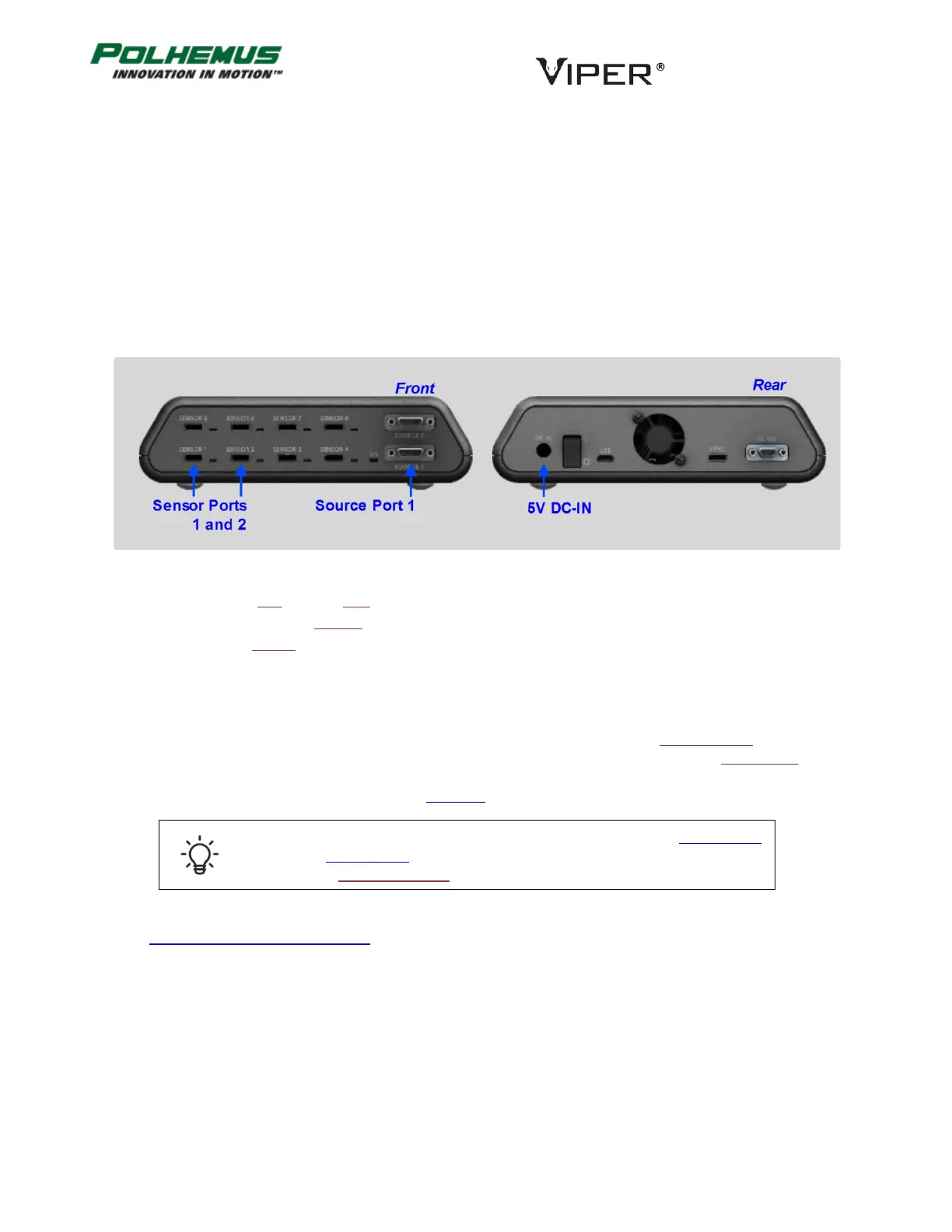
Refer to the figure below for connecting your VIPER™ components together.
1. Place the SEU near the host computer.
2. Attach one or two Sensors in Sensor ports 1 and 2.
3. Attach a Source to Source port 1.
4. Connect the VIPER™ power supply to the 5V DC IN port on the rear panel.
PLACE SOURCE AND SENSOR(S) 3.1.2
When placing Source and Sensors for the first time (when VIPER™ is configured with factory default settings), it is
important to place the Sensors on the +X side of the source. This places the Sensor in the +X hemisphere of the
Source. The +X and +Y axes are identified on the surface of the standard Source cube to help you identify where
the +X side of the Source is. This is illustrated in Figure 11 below.
If your sensor is not in the default +X hemisphere, use the HEMISPHERE
command (Section 4.2.9) to tell VIPER™ which hemisphere the Sensor inhabits
or to turn on Auto-Hemisphere.
See Appendix B SOURCE HEMISPHERES for a detailed discussion of the concept of hemispheres.
FIGURE 10. GETTING STARTED: CONNECTIONS