DESCRIPTION:
DATE:
DRAWING NO:
3of17
SHEET:
REVI SION:
L
NOTE:
Callout letter
and
map to drawing #164201300---6
,,,
041503
A
B
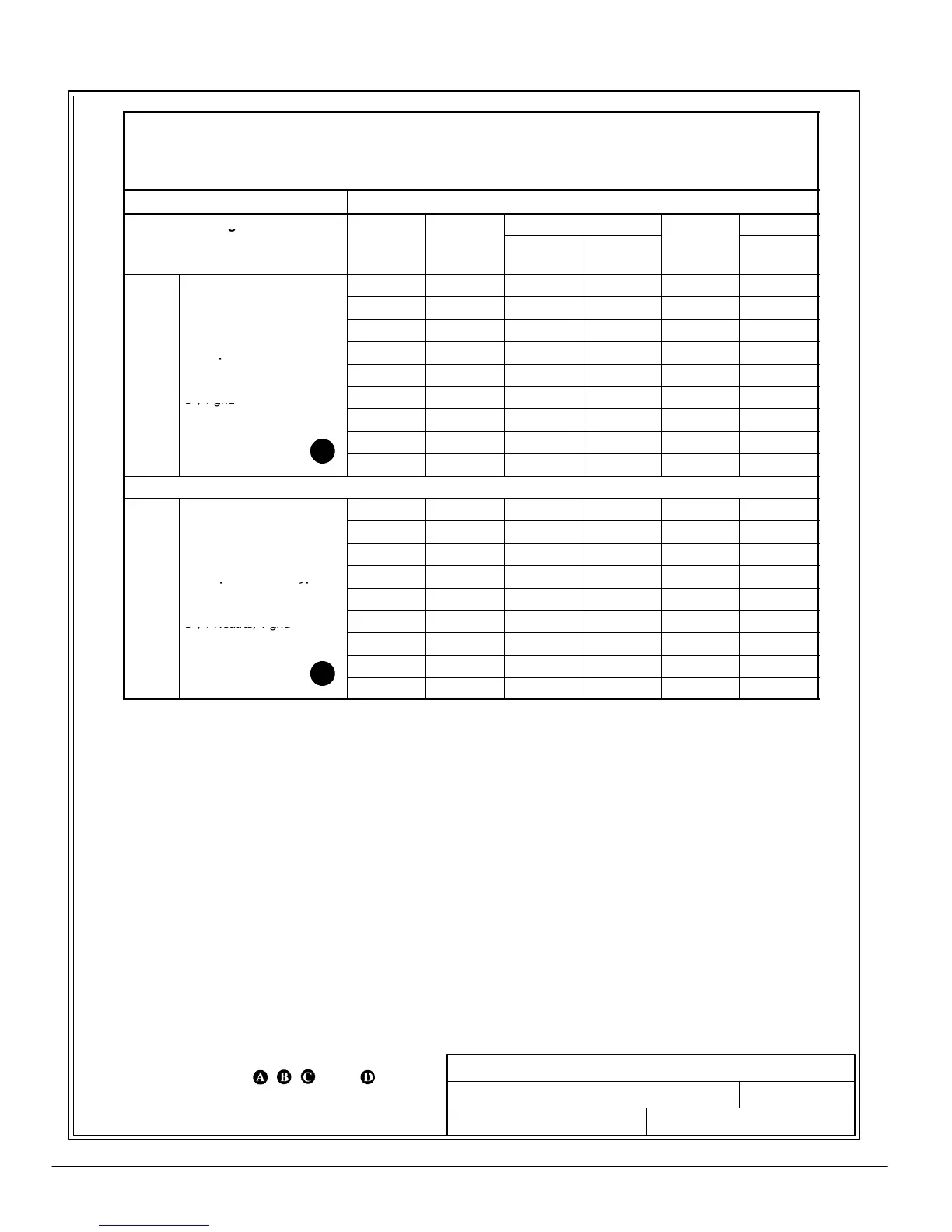
POWER WIRING INSTALLATION NOTES
164201300---1
A --- 4
Powerware 9330 (10 kVA--40 kVA) Installation and Operation
164201300 Rev . N 013004
Table D. Ratings & External Wiring Requirements for
Po werwar e 9330 (10 kVA---20 kV A)
Opt ions Cabin e t INP U T and B Y PASS Trans for m er s
Ratings 50/60 Hz
Basic unit ratings at Voltage
Conductor
0.7 lagging PF load
Series/
Model
kVA/KW
Input Output
npu
Current
(Amps)
Minimum
Size
20/10 10/7 208 208 27.8 8
20/10 10/7 480 208 12 14
20/10 10/7 600 208 9.6 14
AC Input to UP S Rect ifier 20/15 15/10.5 208 208 41.6 6
AC
Transformer
20/15 15/10.5 480 208 18 12
.
m
n.
3,1gnd
20/15 15/10.5 600 208 14.4 12
20/20 20/14 208 208 55.5 4
20/20 20/14 480 208 24 10
20/20 20/14 600 208 19.2 12
20/10 10/7 208 208 27.8 8
20/10 10/7 480 208 12 14
20/10 10/7 600 208 9.6 14
AC Input to UPS Bypass 20/15 15/10.5 208 208 41.6 6
AC
Transformer
20/15 15/10.5 480 208 18 12
u
oa
u
en
3, 1 Neutral, 1 gnd
20/15 15/10.5 600 208 14.4 12
20/20 20/14 208 208 55.5 4
20/20 20/14 480 208 24 10
20/20 20/14 600 208 19.2 12