DESCRIPTION:
DATE:
DRAWING NO:
3of3
UPS SYSTEM CONFIGURATIONS
SHEET:
REVI SION:
N
164201300---5
013004
NOTE 2: Output Voltage must match Bypass
Input Voltage.
NOTE 1: A bypass neutral feeder must be
supplied.
A --- 3 0
Powerware 9330 (10 kVA--40 kVA) Installation and Operation
164201300 Rev . N 013004
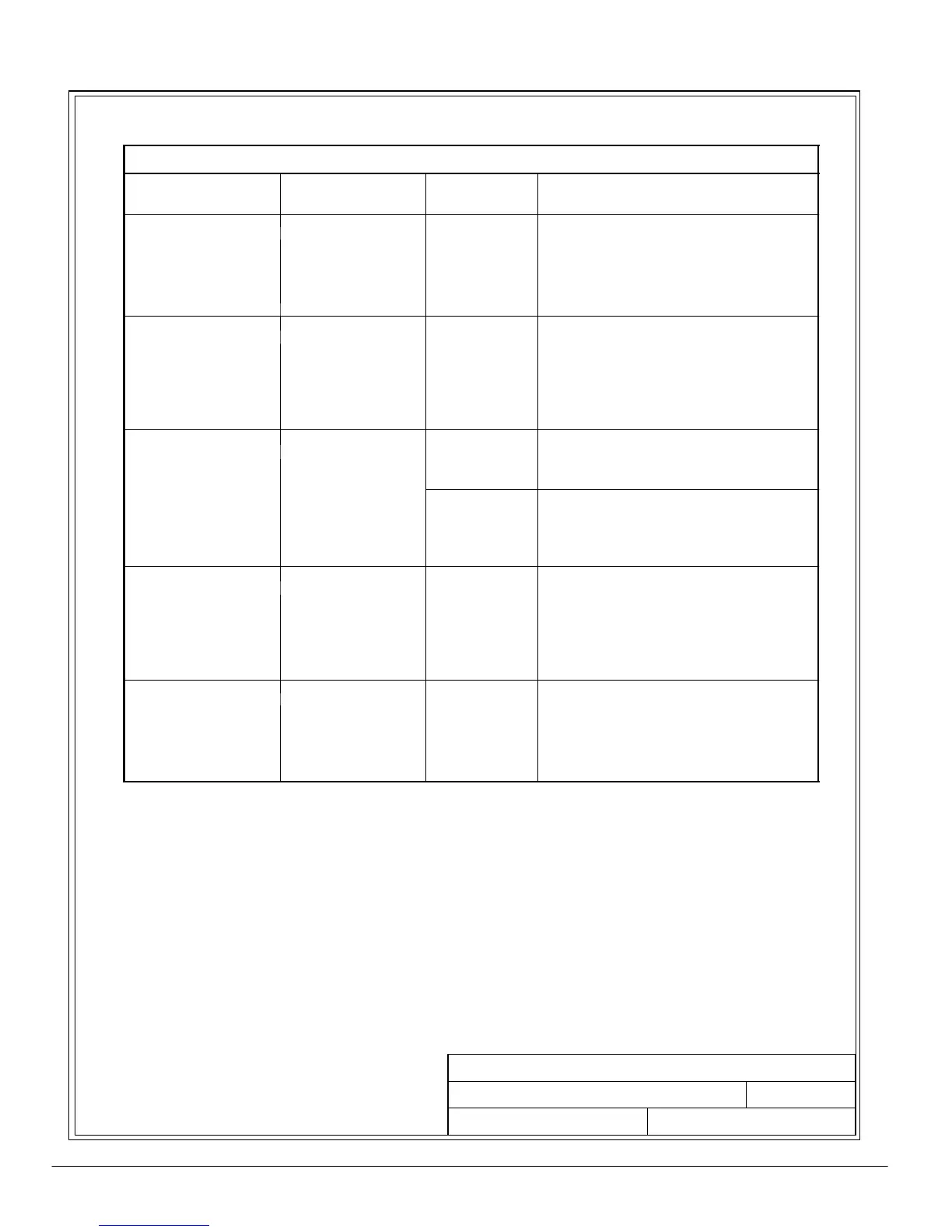
Table AE. UPS System Configurations Schematics (Cont’d)
Schematic D rawing
164201300---7
Powerware
Model
Vin / Vout System Type
9330---40/25
9330---40/30
Single Module --- Reverse Transfer
Sheet 14
9330---40/35
208
480
Single or Dual Feed with Output
uto
Trans
ormer and B
ass Switch
9330---40/40
9330---40/25
208/208
9330---40/30
208
480
480
208
Single Module --- Re
erse Trans
er
Sin
le Feed with In
ut and Out
ut
Sheet 15
9330---40/35
480/480
Isolation Transformers, Bypass Sw itch
9330---40/40
600/480
an
p
ona
s
r
u
on
ane
9330---40/25
Single Module --- Reverse Transfer
9330---40/30
480
480
Single Feed with Input and Output
Auto Transformers and Bypass Switch
Sheet 16
9330---40/35
208 Mains In
Single Module --- Reverse Transfer
Dual Feed with B
ass In
ut and
9330---40/40
480 Bypass In
480 Out
Output Auto Transformers and
Bypass Switch
9330---40/25
208/208
9330---40/30
208
480
480
208
Single Module --- Re
erse Trans
er
Dual Feed with In
ut and Out
ut
Sheet 17
9330---40/35
480/480
Isolation Transformers, Bypass Sw itch
9330---40/40
600/480
an
p
ona
s
r
u
on
ane
9330---40/25
9330---40/30
480 Mains In
ng
e
o
u
e ---
e
erse
rans
er
Dual Feed with Mains In
ut and
Sheet 18
9330---40/35
208 Bypass In
480 Ou
Output Auto Transformers and
9330---40/40
Bypass Switch