4-- 2
Powerware 9330 (10 kVA--40 kVA) Installation and Operation
164201300 Rev . N 013004
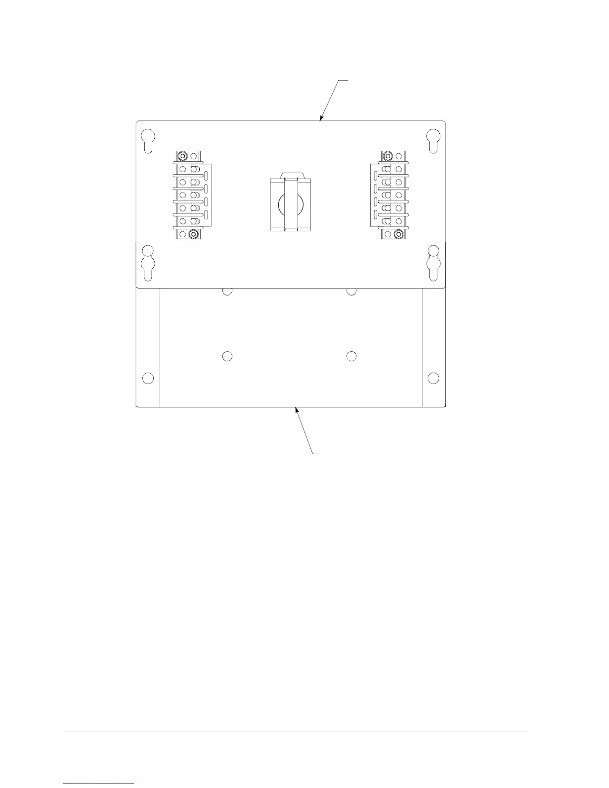
TB2
TB1
COVER
BOTTOM ENCLOSURE
Figure 4---2. Remote EPO Control (inside view of cover and bottom of enclosure)
3. Mount cover to Remote EPO switch enclosure bottom, as shown in
Figure 4---2, for easier wiring.
NOTE: A separate conduit is required for each UPS connected to the Remote EPO
switch.
4. Install wiring from the Remote EPO switch using ½-in. conduit through the
Customer Interface conduit landing plate on the rear of the UPS cabinet. Refer
to Appendix A, Drawing 164201300---8, for conduit landing area and terminal
board location, and Drawing 164201300---2 for terminal wiring assignments.
5. Connect the Remote EPO wiring as shown in Tables 4---1 and 4---2 and Figure
4 --- 2 .
6. If you are installing multiple Remote EPO stations, wire additional stations in
series with the first R emote EPO.