142
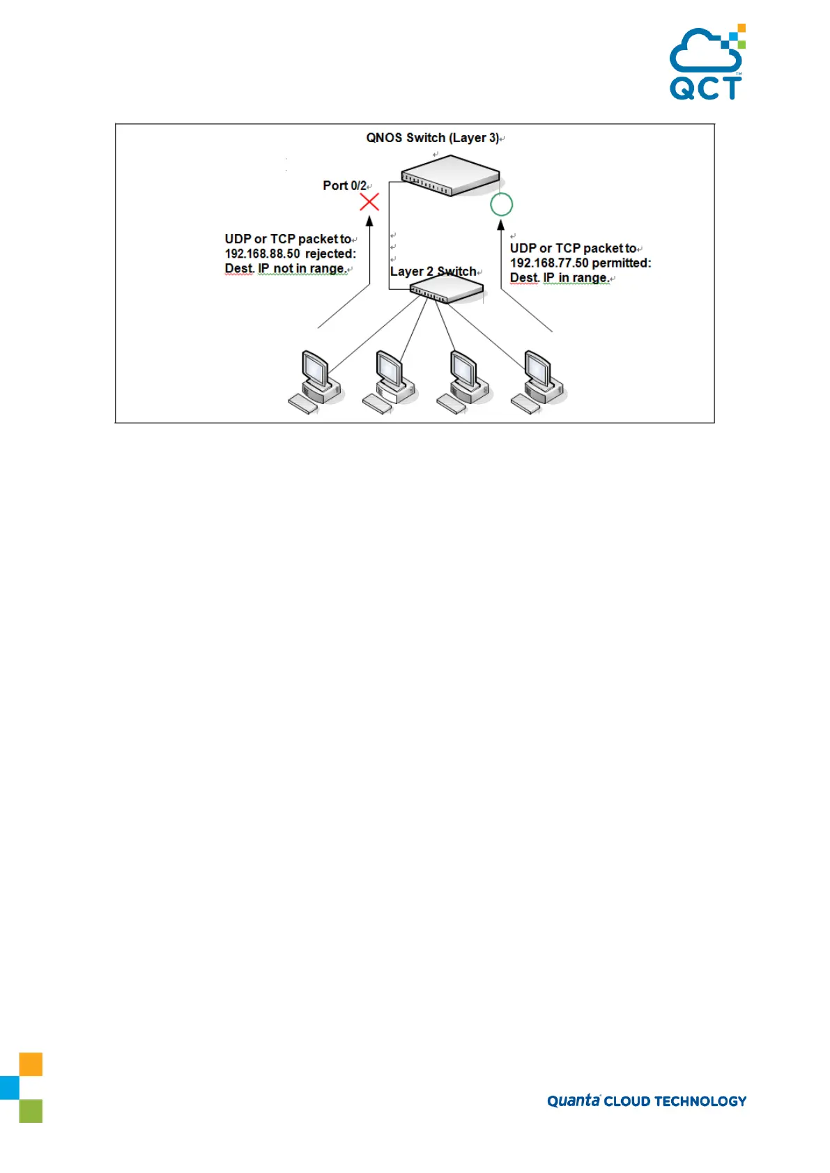
Figure 4-4: IP ACL Example Network Diagram
To configure the switch:
1. Create an extended ACL and configure a rule for the ACL that permits packets carrying TCP traffic that
matches the specified Source IP address (192.168.77.0/24), and sends these packets to the specified
Destination IP address (192.168.77.50).
(QCT) #config
(QCT) (Config)#access-list 100 permit tcp 192.168.77.0 0.0.0.255 192.168.77.50 0.0.0.0
2. Define the rule to set similar conditions for UDP traffic as for TCP traffic.
(QCT) (Config)#access-list 100 permit udp 192.168.77.0 0.0.0.255 192.168.77.3 0.0.0.255
3. Apply the rule to inbound (ingress) traffic on port 2. Only traffic matching the criteria will be accepted on
this port.
(QCT) (Config)#interface 0/2
(QCT) (Interface 0/2)#ip access-group 100 in
(QCT) (Interface 0/2)#exit
4. Verify the configuration.
(QCT) #show ip access-lists 100
ACL ID: 100
Inbound Interface(s): 0/2
Sequence Number: 1
Action.........................................
permit