229
(QCT) (if-vlan10)#ip igmp version 2
(QCT) (if-vlan10)#ip pim
(QCT) (if-vlan10)#exit
7. Configure VLAN 20 as a VLAN routing interface and specify the OSPF area.
(QCT) (Config)#interface vlan 20
(QCT) (if-vlan20)#ip address 192.168.20.4 255.255.255.0
(QCT) (if-vlan20)#ip ospf area 0
8. Enable IGMPv2 and PIM-SM on the VLAN routing interface.
(QCT) (if-vlan20)#ip igmp
(QCT) (if-vlan20)#ip igmp version 2
(QCT) (if-vlan20)#ip pim
(QCT) (if-vlan20)#exit
9. Globally enable IGMP snooping, IP multicast, IGMP, and PIM-SM on the switch.
(QCT) (Config)#ip igmp snooping
(QCT) (Config)#ip multicast
(QCT) (Config)#ip igmp
(QCT) (Config)#ip pim sparse
10. Configure VLAN 10 as the RP and specify the range of multicast groups for PIM-SM to control.
(QCT) (Config)#ip pim rp-address 192.168.10.4 225.0.0.0 240.0.0.0
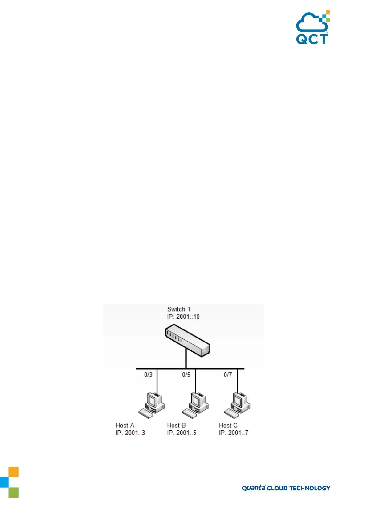
8.3.2. Example 1: MLDv1 Configuration
Figure 8-2: MLD Topology
To configure the switch: