196
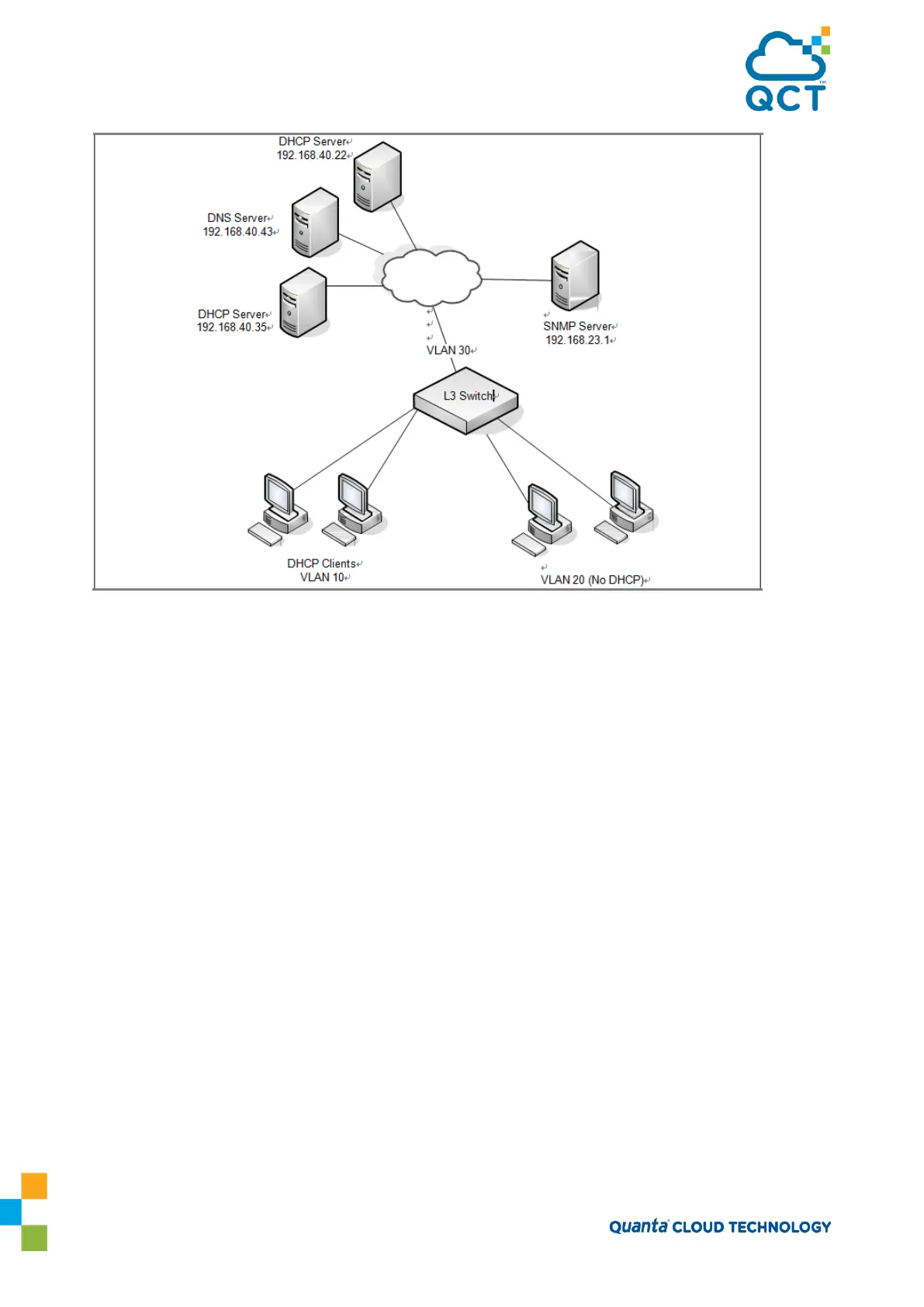
Figure 7-7: L3 Relay Network Diagram
This example assumes that multiple VLAN routing interfaces have been created and configured with IP
addresses.
To configure the switch:
1. Enable IP helper on the switch.
(QCT) #config
(QCT) (Config)#ip helper enable
2. Relay DHCP packets received on VLAN 10 to 192.168.40.35
(QCT) (Config)#interface vlan 10
(QCT) (if-vlan10)#ip helper-address 192.168.40.35 dhcp
3. Relay DNS packets received on VLAN 10 to 192.168.40.43
(QCT) (if-vlan10)#ip helper-address 192.168.40.35 domain
(QCT) (if-vlan10)#exit
4. Relay SNMP traps (port 162) received on VLAN 20 to 192.168.23.1
(QCT) (Config)#interface vlan 20
(QCT) (if-vlan20)#ip helper-address 192.168.23.1 162
5. The clients on VLAN 20 have statically-configured network information, so the switch is configured to
drop DHCP packets received on VLAN 20