91
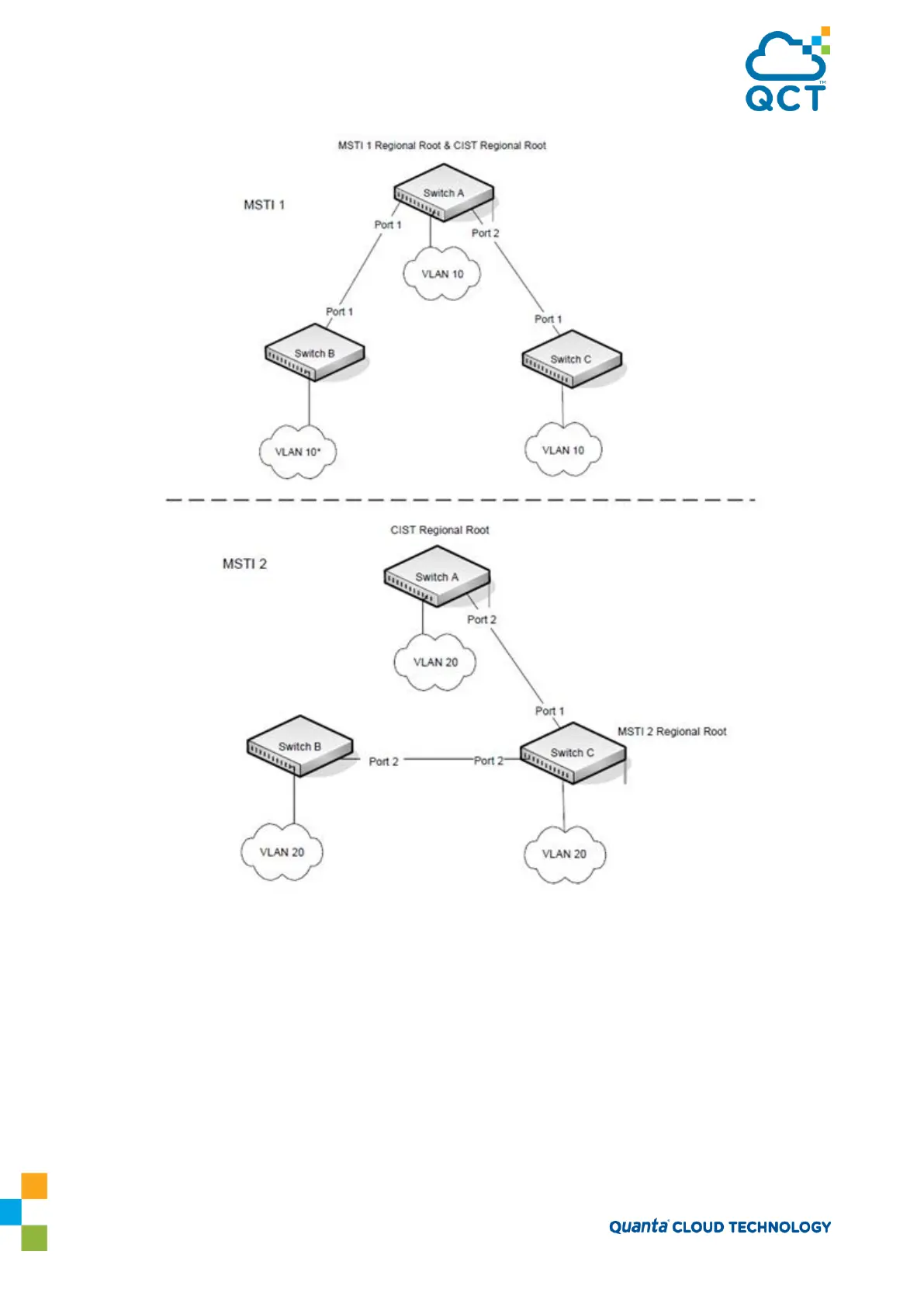
Figure 3-13: Logical MSTP Environment
For MSTP to correctly establish the different MSTIs as above, some additional changes are required. For
example, the configuration would have to be the same on each and every bridge. That means that Switch B
would have to add VLAN 10 to its list of supported VLANs. This is necessary with MSTP to allow the
formation of Regions made up of all switches that exchange the same MST Configuration Identifier. It is
within only these MST Regions that multiple instances can exist. It will also allow the election of Regional
Root Bridges for each instance. One common and internal spanning tree (CIST) Regional Root for the CIST
and an MSTI Regional Root Bridge per instance will enable the possibility of alternate paths through each
Region. Above Switch A is elected as both the MSTI 1 Regional Root and the CIST Regional Root Bridge, and
after adjusting the Bridge Priority on Switch C in MSTI 2, it would be elected as the MSTI 2 Regional Root.