242
(QCT) (Config)#traffic-class-group min-bandwidth 0 0 0
After performing Step 1–Step 9, the data traffic with an 802.1p priority is sent through TCG1, and 45% of the
bandwidth (excluding TCG0 bandwidth) is reserved for TCG1. This protects the TCG1 traffic from traffic that
is transmitted on TCG2. Any burst in traffic being transmitted in TCG2 does not affect traffic in TCG1. If TCG2
is not being utilized to the full potential then TCG1 can still use that bandwidth for transmitting TCG1 traffic.
With the configuration in this example, TCG0 with strict priority gets highest priority and can consume the
full bandwidth of the pipeline. TCG1 and TCG2 share the remaining bandwidth after TCG0 consumes its
share of the pipeline.
Based on this configuration, when the switch sends the configuration ETS TLVs to the peer, the values that are
given to DCBX are as follows:
Willing
Bit
—
This bit is set to TRUE for auto-upstream interfaces if there is no configuration
source or
FALSE if there is a configuration source, and FALSE for auto-downstream and manual ports.
Credit-based Shaper support and Max
TC
—
These are platform-specific values.
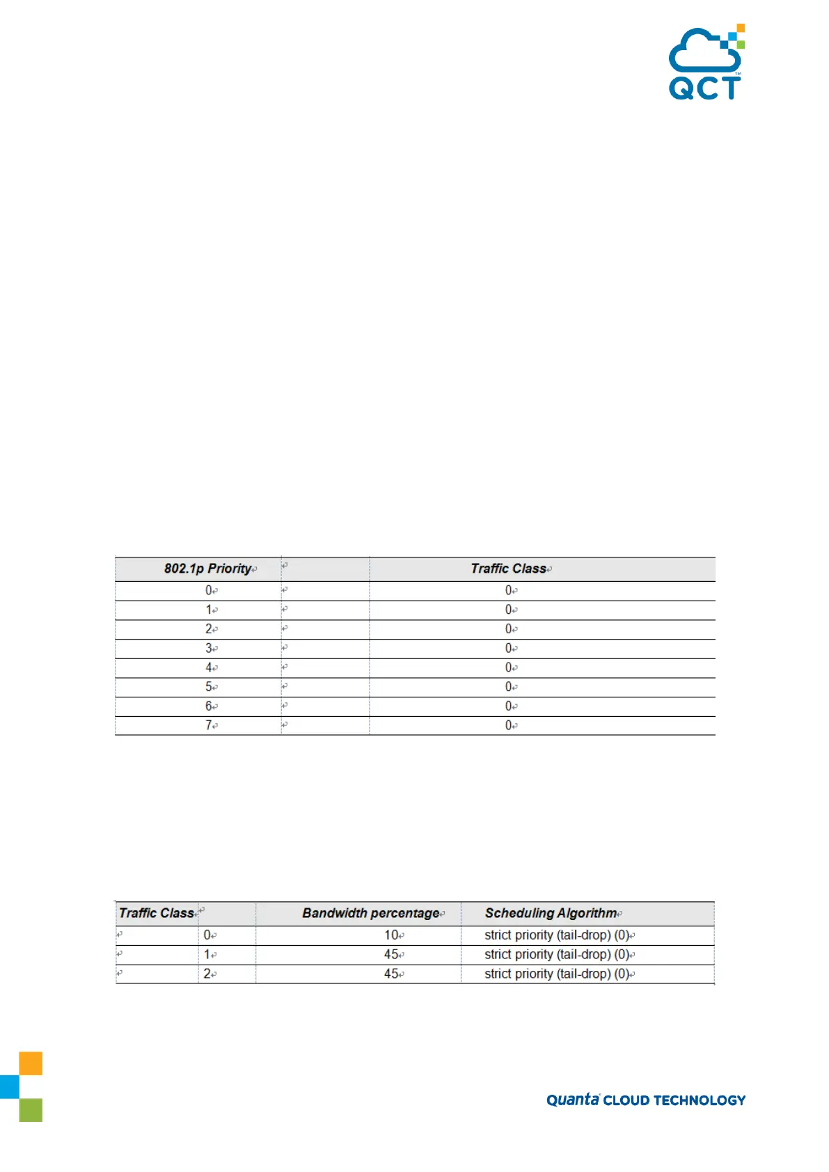
Priority Assignment
Table
—
Table 25 contains the default values advertised by DCBX to the
peer DCBX device. If available, the mapping translated from the configuration source is used.
This table defines the mapping between the egress Traffic Class Group and ingress 802.1p
priority.
Table 9-2: 802.1p-to-TCG Mapping
TC Bandwidth And TSA Assignment
Table
—
Table 26 contains the default values advertised
by DCBX to the peer DCBX device. If available, the assignments translated from the
configuration source is used. This table defines the bandwidth allocated to each Traffic Class
Group and the respective scheduling algorithm for each TCG; the scheduling algorithm is
enumerated in the IEEE 802.1Q specification.
Table 9-3: TCG Bandwidth and Scheduling