188
VRRP with Route and Interface Tracking
7.3.2.1. VRRP with Load Sharing
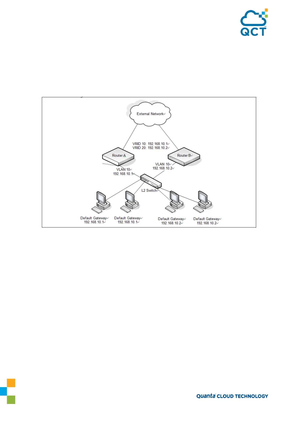
In Figure 28, two L3 switches are performing the routing for network clients. Router A is the default gateway
for some clients, and Router B is the default gateway for other clients.
Figure 7-5: VRRP with Load Sharing Network Diagram
This example configures two VRRP groups on each router. Router A is the VRRP master for the VRRP group
with VRID 10 and the backup for VRID 20. Router B is the VRRP master for VRID 20 and the backup for VRID
10. If Router A fails, Router B will become the master of VRID 10 and will use the virtual IP address
192.168.10.1. Traffic from the clients configured to use Router A as the default gateway will be handled by
Router B.
To configure Router A:
1. Create and configure the VLAN routing interface to use as the default gateway for network clients. This
example assumes all other routing interfaces, such as the interface to the external network, have been
configured.
(QCT) (Config)#interface vlan 10
(QCT) (if-vlan10)#ip address 192.168.10.1 255.255.255.0
(QCT) (if-vlan10)#exit
2. Enable routing for the switch.
(QCT) (Config)#ip routing
3. Enable VRRP for the switch.