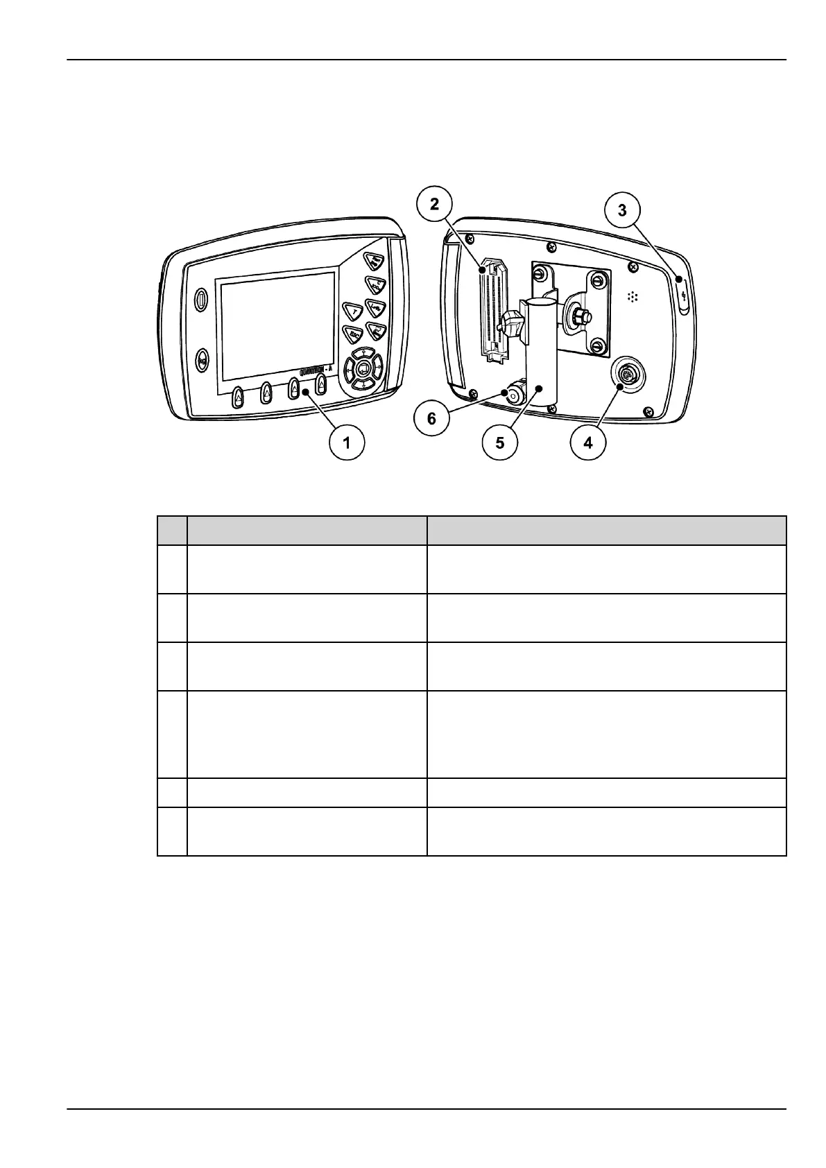
2.2 Layout of the control unit
Fig. 1: Control unit QUANTRON-A
No. Designation Function
1 Control panel Including membrane keys to operate the device and the
display for operating screens
2 Plug connector for connecting the
machine cable
39-pin plug connector for connecting the machine cable
to sensors and servomotors (SpeedServos)
3 USB port with cover For updating the PC. The cover serves as protection
against dirt
4 V24 data port Serial interface (RS232) with LH 5000 and ASD protocol,
designed for connecting a Y-RS232 cable to a remote
terminal. Plug connector (DIN 9684-1/ISO 11786) for
connecting the 7-pin to 8-pin cable for the speed sensor.
5 Mounting bracket Attachment of the control unit to the tractor
6 Power supply 3-pin plug connector conforming to DIN 9680 ISO 12369
for connecting the power supply
2. Layout and function
QUANTRON-A AXIS/MDS 5902662
11