Chapter 3: Operation 3-25
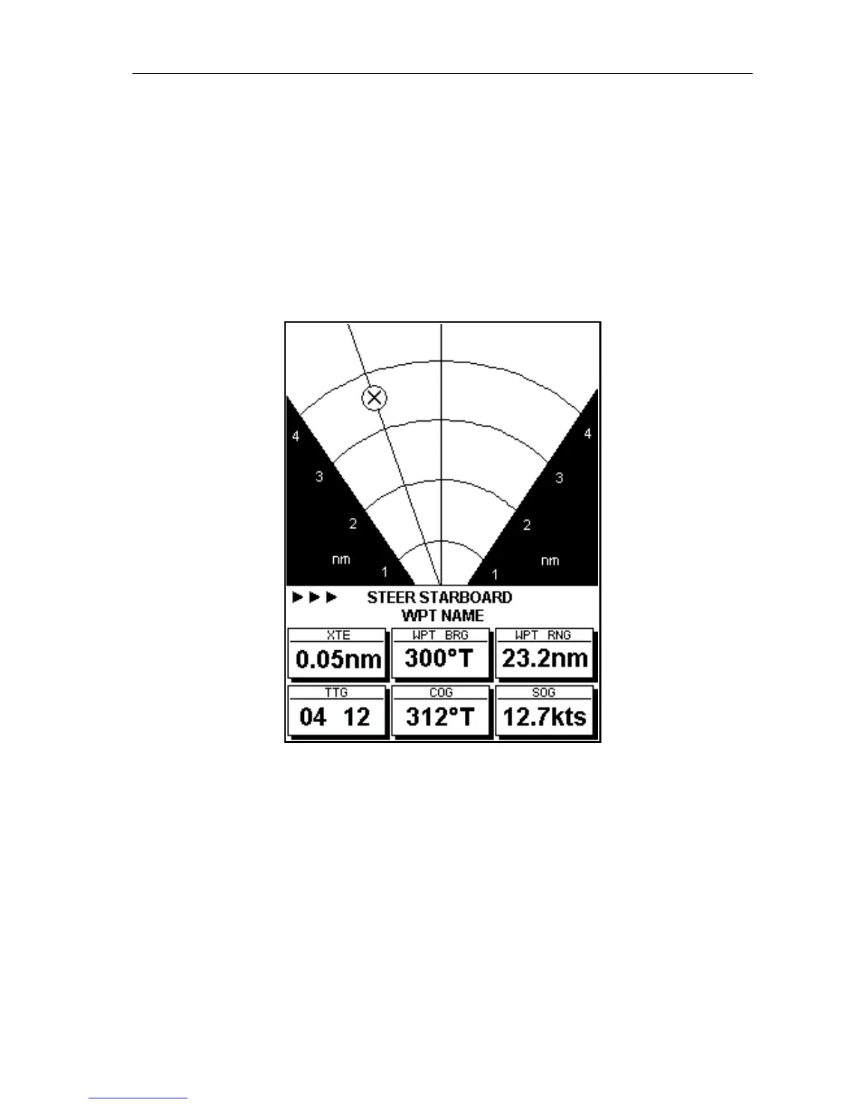
The first arrow is shown when the XTE reaches 0.01nm, the second
at.05nm and subsequently at 0.1nm intervals.
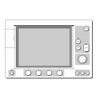
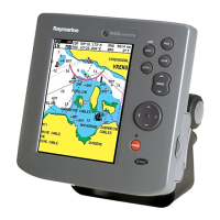
BDI Display
The BDI display shows deviation from the bearing to waypoint and
distance to waypoint. Cross track Error, Bearing to Waypoint, Distance to
Waypoint, Time to Go, COG and SOG are also shown. Time To Go is
calculated on the basis of distance to destination and velocity made good
towards destination (Figure 3-41).
Figure 3-41: BDI Display
The line to the waypoint symbol is shown at an angle equal to the
difference between the COG and the Bearing to Waypoint.
The range scale automatically scales for distance. The ranges shown are
1nm, 4nm, 20nm, 40nm, 100nm, 200nm, 400nm, 1000nm, 2000nm,
4000nm. In each case the range scale has graduations at ¼, ½ and ¾ of the
current scale.
The steering instruction is
STEER STARBOARD if the waypoint line is 1° or
more to port,
STEER PORT if the waypoint line is 1° or more to starboard or
ON COURSE if the waypoint line is dead ahead. If no GOTO or follow is in
progress, the steering instruction is
NO TARGET, no steering arrows are
shown, but the rhumb line indicator is shown.
D4701_1
 Loading...