Chapter 5: Installation 5-1
Chapter 5: Installation
5.1 Introduction
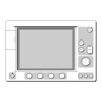
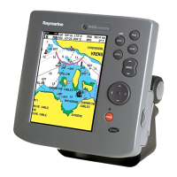
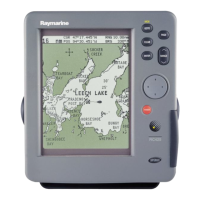
This chapter provides instructions to assist in planning the installation of
the Raychart 425 Chartplotter aboard your vessel.
Note: If you wish to practice using the Raychart 425 before installation,
you can connect it, via a 1A quick blow fuse, to a 12VDC power supply
and operate it using the simulator mode, as described in Chapter 2:Get-
ting Started.
EMC Installation Guidelines
All Raymarine equipment and accessories are designed to the best
industry standards for use in the recreational marine environment.
Their design and manufacture conforms to the appropriate
Electromagnetic Compatibility (EMC) standards, but correct installation
is required to ensure that performance is not compromised. Although
every effort has been taken to ensure that they will perform under all
conditions, it is important to understand what factors could affect the
operation of the product.
The guidelines given here describe the conditions for optimum EMC
performance, but it is recognized that it may not be possible to meet all of
these conditions in all situations. To ensure the best possible conditions
for EMC performance within the constraints imposed by any location,
always ensure the maximum separation possible between different items
of electrical equipment.
For optimum EMC performance, it is recommended that wherever
possible:
• Raymarine equipment and cables connected to it are:
• At least 3 ft (1 m) from any equipment transmitting or cables car-
rying radio signals e.g. VHF radios, cables and antennas. In the
case of SSB radios, the distance should be increased to 7 ft (2 m).
• More than 7 ft (2 m) from the path of a radar beam. A radar beam
can normally be assumed to spread 20 degrees above and below
the radiating element.
• The equipment is supplied from a separate battery from that used for
engine start. Voltage drops below 10 V, and starter motor transients,
can cause the equipment to reset. This will not damage the equip-
ment, but may cause the loss of some information and may change the
operating mode.
 Loading...