MANUAL – REFLEX EZ-TRAC™ | 63
with the wedge down in the borehole. The diameter and threads of
the mule shoe sleeve should be exactly the same as the drill rods
being used. The mule shoe sleeve is provided in 0.6 m/2 ft sections.
When surveying relative to Magnetic Tool Face, six aluminium
extension rods and nine meters of non-magnetic drill rods are also
required.
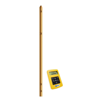
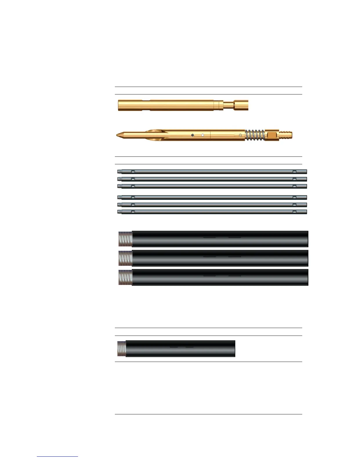
Figure 74 Orientation equipment
Orientation bull plug
Orientation mule shoe
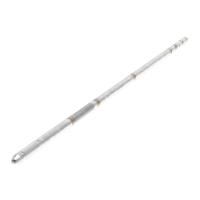
Figure 75 Additional equipment for Magnetic Tool Face mode
6 aluminium extension rods
9 meters of non-magnetic drill rods
10.4.1 Mule shoe sleeve
The direction indicator (pin) on the mule shoe sleeve shall be aligned
with the kick direction of the wedge.
Figure 76 Mule shoe sleeve
Align mule shoe sleeve
1. Set out the wedge horizontally on the rod rack or the ground, with
its required kick direction pointing vertically upwards.
2. Thread the mule shoe sleeve onto the wedge.
3. The mule shoe sleeve is now ready for zeroing, as described in
the section Zeroing below.