MANUAL – REFLEX EZ-TRAC™ | 69
Align survey system
1. Make sure that a reference mark on the outside of the instrument
was established when the zeroing procedure was performed. If
not, the zeroing has to be redone.
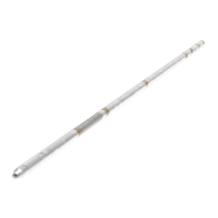
2. Using open end wrenches, join three aluminium extension rods
together. Use the machined slots to position the wrenches. The
total assembled length should be 4.5 m/15 feet.
3. Unthread the mule shoe from the bull plug and ensure that it is
clean and free from roughness.
4. Thread the mule shoe onto the box end of the three assembled
aluminium extension rods and tighten.
5. Thread the bull plug, with the
REFLEX EZ-TRAC
®
attached, onto the
pin end of the three aluminium extension rods and tighten.
6. Slide the instrument assembly into the mule shoe sleeve (see
section Mule shoe sleeve above).
7. Verify that the mule shoe rotates as necessary and that it slides in
correctly over the pin in the mule shoe sleeve.
8. Ensure that the locking nut of the bull plug is loose.
9. Rotate the instrument assembly until the reference mark on the
outside of the
REFLEX EZ-TRAC
®
is aligned with the kick direction
of the wedge.
10. Tighten the locking nut of the bull plug. Ensure that the alignment
remains.
11. Remove the survey system from the mule shoe sleeve assembly.
In order to avoid magnetic interference from the drill rods, another
three aluminium extension rods are attached to the upper end of the
instrument.
Assemble survey system
1. Using open end wrenches, join the three aluminium extension
rods together. Use the machined slots to position the wrenches.
The total assembled length should be 4.5 m/15 feet.
2. Thread the aluminium extension rod package into the top coupling
of the instrument.
10.6.4 Load tell tale
A lead tell tale is loaded in the mule shoe, allowing confirmation that
the mule shoe has been correctly positioned in the mule shoe sleeve
during the downhole survey. The internal pin of the mule shoe sleeve
leaves an impression on the tell tale if the mule shoe has positioned
accurately.
Figure 81 Load lead tell tale