Do you have a question about the Reflex EZ-TRAC and is the answer not in the manual?
Provides contact details for the REFLEX™ headquarters in Perth, Western Australia.
Explains the use of notes of caution and hints within the manual.
An overview of the REFLEX EZ-TRAC™ instrument and its capabilities for borehole surveying.
Details Single Shot, Multi Shot, and Orientation surveys performed by the instrument.
Explains how magnetometers and accelerometers are used for measurements.
Discusses factors affecting survey accuracy and sources of error.
Provides guidelines for returning the instrument for service or repair.
Explains that boreholes inherently deviate from their planned path.
Details how spatial coordinates are calculated using mathematical algorithms.
Discusses determining the direction of downhole objects and tools.
Overview of the survey results provided by REFLEX™™ instruments.
Explains the principles of magnetism and how it affects measurements.
Details the function of fluxgate magnetometers in measuring Earth's magnetic field.
Explains MEMS accelerometers for measuring dip and gravity tool face.
Discusses the design for accurate data and typical measurement errors.
Explains how magnetic interference can lead to incorrect measurements.
Details precautions to avoid magnetic interference from in-hole ferrous metals.
Presents a map of Earth's total magnetic field intensity for reference.
Presents a map of Earth's magnetic inclination (dip) for reference.
Shows the annual rate of change for magnetic declination.
Lists the basic survey data measured and displayed by REFLEX™™ instruments.
Defines dip (inclination) and azimuth (direction) of the borehole.
Explains the calculation of total magnetic field strength and magnetic dip.
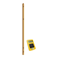
Details the components of the REFLEX EZ-TRAC™ instrument probe.
Describes the REFLEX™ EZ-COM handheld control unit.
Describes equipment specifically for orientation surveys.
Lists part numbers for ordering REFLEX EZ-TRAC™ and EZ-COM components.
Describes the REFLEX EZ-COM handheld unit and its IR communication.
Details the function of the power, backlight, and navigation keys on the keypad.
Explains how to enter survey names and other data using the character list.
Describes the infrared communication between the control unit and the instrument.
Accesses Single Shot, Multi Shot, and Orientation surveying functions.
Provides access to all stored Single Shot, Multi Shot, and Orientation surveys.
Accesses settings for units, magnetic reference, date/time, and license key.
Describes how to find the serial number of the REFLEX EZ-COM unit.
Guides on entering a license key to enable the Multi Shot feature.
Explains how to disable the Multi Shot functionality.
Details how Multi Shot surveys are stored and named (e.g., Test and Test_R).
Explains how survey results are displayed and indicators for magnetic interference.
Allows setting linear, angular, and temperature units for survey results.
Displays the currently set magnetic reference values.
Guides on how to register a new magnetic reference in a non-magnetic location.
Explains how to download the measured magnetic reference values.
Displays the current date and time settings of the unit.
Procedure to set or change the current date.
Procedure to set or change the current time.
Describes general messages and warnings that can appear during surveys.
Message indicating a survey name already exists and requires a unique name.
Message appearing when the instrument is in use and a connection is attempted.
Message displayed when a survey is cancelled, warning of data loss.
Prompts to delete the oldest survey data to free up memory space.
Indicates the maximum survey limit has been reached, suggesting deletion.
Confirms deletion of oldest surveys when the maximum number is exceeded.
Warning if survey depth is less than the previous station in an existing survey.
Message when a survey depth already exists, prompting re-survey.
Indicates completion of a reverse survey measurement.
Warning about using a stored zeroing value with a different tool serial number.
Warning about losing survey results and zeroing when cancelling an orientation survey.
Deciding on surveying method and necessary equipment preparations.
Instructions for registering a magnetic reference to identify interference.
Guides on setting up a new Single Shot survey or adding to an existing one.
Procedure for entering survey name and depth for a new Single Shot survey.
Steps for positioning and measuring a survey station for Single Shot.
Steps for positioning and measuring survey stations for Multi Shot.
Provides instructions on how to perform an Orientation survey.
Establishes orientation or direction of downhole objects like wedges or tools.
Explains orientation surveys using Gravity Tool Face or Magnetic Tool Face.
Describes the mule shoe sleeve and how to align it with the wedge.
Procedure for setting the reference position to zero for orientation surveys.
Details positioning for zeroing using the gravity method for specific inclinations.
Initializes the instrument for downhole survey, including serial number check.
Assembling the survey system for Gravity Tool Face mode.
Assembling the system with extension rods for Magnetic Tool Face mode.
Entering a desired toolface value to adjust orientation if needed.
Ending the survey and saving results, including orientation and inclination.
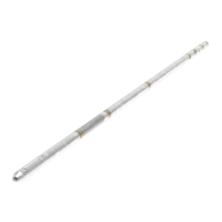
Details the running gear used for REFLEX EZ-TRAC™ surveys.
Tips for assembling running gear, including sealing rings and rod tightness.
Checks and cleaning required for running gear before and after surveys.
Specifies the use of aluminium extension rods to avoid magnetic interference.
Assembly of pin spear landing collar with extension rods.
Assembly of pin spear coupling and landing collar.
Method using wireline through drill string, common for Single Shot surveys.
Using gravity to lower the survey system, suitable for inclined boreholes.
Using wireline with gravity for extra safety when lowering the system.
Method for boreholes not inclined enough or directed upwards, using core tube.
Surveying downwards in open holes using gravity, swivel, and winch.
Surveying upwards in open holes using push rods and an adapter.
Achieving azimuth and inclination readings in an RC environment with specific rod setups.
Achieving inclination readings in an RC environment, unaffected by magnetism.
Describes the content and naming conventions of survey data files.
Details the two data files (.MLH, .MLR) generated by Single Shot surveys.
Details the data files generated by Multi Shot and Reversed Multi Shot surveys.
Details the two data files (.ORH, .ORR) generated by Orientation surveys.
Notes on limitations of REFLEX SProcess regarding Orientation and older Single Shot files.
Highlights the importance of treating the instrument as a precision device.
Emphasizes routine care of the instrument before and after each survey.
Checks for sealing rings and threads, and lubrication advice.
Steps for checking and cleaning equipment after completing a survey.
Describes how to replace the battery of the REFLEX EZ-TRAC™ and EZ-COM units.
Procedure for replacing the battery in the REFLEX EZ-TRAC™ instrument.
Steps to unscrew the battery housing and disconnect the old battery.
Steps to connect a new battery and refit the housing.
Steps to power off, unscrew, and replace the battery in the REFLEX EZ-COM unit.
Recommends annual calibration by REFLEX™™ personnel for optimal performance.
Instructions for contacting REFLEX™™ for service or malfunction.
Defines the x-axis in a geographical coordinate system (north-south).
Defines the y-axis in a geographical coordinate system (east-west).
Defines the z-axis for elevation, with positive upwards convention.
The borehole direction measured from north against east (0-360°).
Explains that the license key is assigned to the serial number of each unit.
Instructions for entering the license key to enable Multi Shot functionality.
| Brand | Reflex |
|---|---|
| Model | EZ-TRAC |
| Category | Measuring Instruments |
| Language | English |