INSTALLATION PROCEDURE
18
2012-2015 Reliable Controls Corporation
EIA-485 NETWORK WIRING PROCEDURES
TO CONNECT THE SMART-SPACE CONTROLLER TO AN EIA-485 NETWORK
1 Reliable Controls recommends using 2-wire, shielded, low capacitance (less
than 25 pf/ft. nominal), 22 AWG, 108 Ω impedance, certified communication
cable for connecting the SMART-Space Controller to an EIA-485 network. The
Connect-Air part number for the cable tested and approved by Reliable Controls
for this application is W223C-2005RSPB.
2 To facilitate daisy-chaining of networked SMART-Space Controllers, two sets of
terminals are provided for terminating EIA-485 cables. The two sets of terminals
are connected to each other on the circuit board.
3 It is not necessary to terminate the REF pins, as the EIA-485 A and B voltages
are referenced to ground via the grounded return wire to the 24 VAC power
transformer.
4 When two EIA-485 cables are connected to a SMART-Space Controller, the two
shields must be connected together. Each continuous section of shield must be
grounded in one location only.
5 The End-Of-Line (EOL) switch must be set to the On position on the two EIA-485
devices located at the physical extremities of each separate EIA-485 network.
The SMART-Space Controller includes an EOL switch located beneath the black
terminal strip. All MACH-System controllers use either jumpers or DIP switches
to set the EOL position.
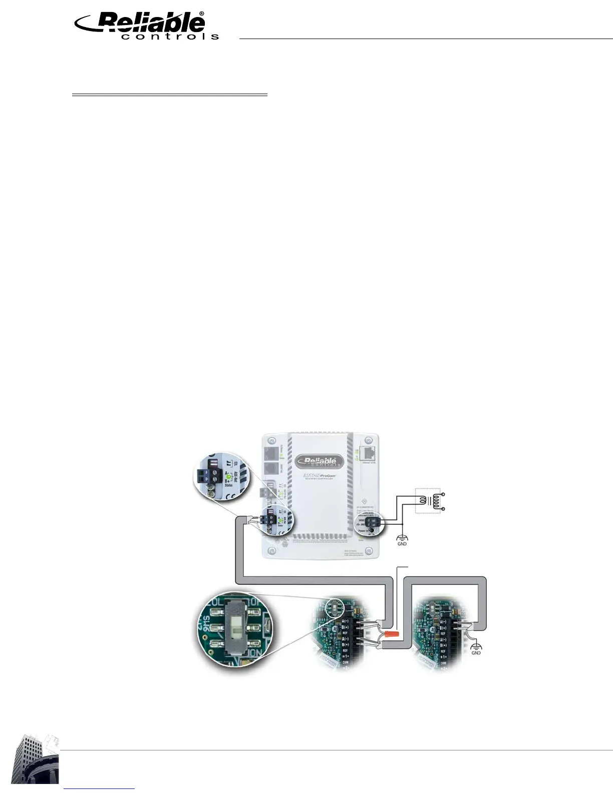
FIGURE 13: EOL AND SHIELD CONFIGURATION
Transformer
24 VAC
120 VAC
One side of 24 VAC power grounded
Cable shield connected
with wire nut
EOL switch OFF
EOL switch ON
Shield
grounded
once
SSC #1 SSC #n
EOL switches In