10A-129
ENGINE AND CYLINDER BLOCK ASSEMBLY
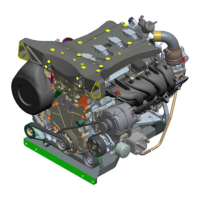
Engine/gearbox assembly: Removal - Refitting
K9K, and 830 or 832
10A
-from the opening of the "dehydrator reservoir -
compressor" connecting pipe.
a Refit a new seal on the "dehydrator reservoir - com-
pressor" connecting pipe on the compressor side.
a Lubricate the new seals with the recommended air
conditioning oil to make fitting easier (see Air condi-
tioning: Parts and consumables for the repair
work) (62A, Air conditioning).
a Couple the "dehydrator reservoir - compressor" con-
necting pipe to the compressor.
a Torque tighten the bolt of the "dehydrator reser-
voir - compressor" connecting pipe on the com-
pressor (8 N.m).
a Remove the blanking plug
-from the opening of the clutch master cylinder,
-from the opening of the clutch pipe.
a Connect the hydraulic clutch pipe on the clutch mas-
ter cylinder.
a Remove the tool (Ms. 583) from the clutch master
cylinder supply pipe.
a Bleed the hydraulic clutch circuit (see Clutch cir-
cuit: Bleeding) (37A, Mechanical component con-
trols).
a Fit the manual gear selector cables.
a Clip the manual gear selector cables:
-on the sheath stop,
-on the anchoring ball joints.
a Connect the brake servo pipe union to the vacuum
pump.
a Position the diesel heater wiring.
a Clip:
-the diesel heater wiring on the radiator mounting
cross member,
-the diesel heater wiring on the "condenser - evapo-
rator" connecting pipe,
-the diesel heater wiring on the body.
a Connect the diesel heater connector.
a Fit the engine fuse box.
a Refit:
-the engine fuse box nuts,
-the engine fuse box bolt.
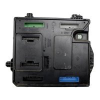
a Connect the Protection and Switching Unit connec-
tors.
a Refit the Protection and Switching Unit cover.
a Fit the earth cable on the vehicle body.
a Torque tighten the earth cable nut on the body (8
N.m).
a Connect the pre-postheating unit connector.
a Fit the air resonator support.
a Refit the nuts of the air resonator support.
a Refit the air resonator (see 12A, Fuel mixture, Air
resonator: Removal - Refitting, page 12A-1) .
a Clip the power wiring channel on the left-hand sus-
pended engine mounting.
a Position the power cables.
a Refit the power cable nuts on the battery disconnec-
tion unit.
a Clip the battery disconnection unit wiring onto the
battery disconnection unit.
a Connect:
- the connectors of the battery disconnection unit,
- the turbocharging pressure regulation solenoid val-
ve connector.
a Refit the front end panel.
a Fit the motor-driven fan assembly wiring.
a Clip:
- the relay unit on the front end panel,
- the fan assembly wiring on the fan assembly.
a Connect:
- the fan assembly connector,
- the fan assembly resistor connector.
a Refit:
- the lower bolts from the front end panel,
- the front end panel upper bolts,
- the front end panel clips,
- the bolts of the fan assembly wiring channel on the
front end panel.
a Clip:
-the expansion bottle top cooling hose on the front
end panel,
- the wiring of the front impact cross member on the
front end panel.
K9K, and 830