10A-154
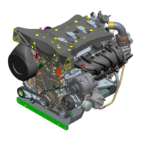
ENGINE AND CYLINDER BLOCK ASSEMBLY
Engine/gearbox assembly: Removal - Refitting
F4R
10A
-the petrol vapour rebreathing pipe,
-the cooling hoses to the heater matrix,
-the expansion bottle bottom cooling hose.
a Fit:
-the heater matrix cooling hose clips using the tool
(Mot. 1448),
-the clip of the expansion bottle bottom cooling hose
using the tool (Mot. 1448).
a Remove the blanking plugs.
a Lubricate a new seal with the recommended air con-
ditioning oil to make fitting easier (see Air conditio-
ning: Parts and consumables for the repair
work) (62A, Air conditioning).
a Fit a new seal on the « intermediate pipe -
compressor » connecting pipe.
a Couple the « intermediate pipe - compressor » con-
necting pipe.
a Refit the bolt of the « intermediate pipe -
compressor » connecting pipe.
a Torque tighten the bolt of the connecting pipe
between the « intermediate pipe - compressor »
(8 N.m).
a Fit the brake servo vacuum pipe.
a Clip:
-brake servo vacuum pipe ,
-the control cables on the manual gearbox.
a Refit the hydraulic clutch pipe (see Clutch circuit:
Removal - Refitting) (37A, Mechanical component
controls).
a Fit:
-the engine fuse box,
-the engine wiring.
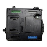
a Connect the Protection and Switching Unit connec-
tors.
a Fit the protection and switching unit.
a Refit:
- the Protection and Switching Unit cover,
- the earth cable nut on the body.
a Torque tighten the earth cable nut on the body (8
N.m).
a Refit the air resonator (see 12A, Fuel mixture, Air
resonator: Removal - Refitting, page 12A-1) .
a Clip the power wiring channel onto the left-hand sus-
pended engine mounting.
a Position the power cables.
a Refit the power cable nuts on the battery disconnec-
tion unit.
a Torque tighten the power cable nuts on the batte-
ry disconnection unit (8 N.m).
a Clip on the wiring of the offset positive terminal.
a Connect the connectors of the battery disconnection
unit.
a Refit the front end panel.
a Clip:
- the relay unit on the front end panel,
- the fan assembly wiring.
a Connect:
- the fan unit resistor connector,
- the motor-driven fan assembly connector.
a Refit:
- the lower bolts from the front end panel,
- the front end panel upper bolts,
- the front end panel clips,
- the bolts of the fan assembly wiring channel.
a Clip:
- the wiring to the front end panel,
- the expansion bottle top cooling hose to the front
impact cross member.
a Connect:
- the radiator bottom cooling hose,
- the expansion bottle top cooling hose,
- the radiator top cooling hose.
WARNING
Do not remove the blanking plugs from each
component until the last moment.
Also, do not remove the components from their
packaging until they are to be fitted to the vehi-
cle.
WARNING
To avoid any leaks, check that the pipe surface is
sound before positioning the new seal. The sur-
face must be clean and scratch free.