PG-FP5 CHAPTER 5 EXAMPLE OF OPERATION USING PROGRAMMING GUI
R20UT0008EJ0400 Rev. 4.00 Page 111 of 240
Jul 15, 2010
in the message display, indicating that the FP5 is ready for operation. If not, the cause may be a defect in the
FP5, so consult a Renesas Electronics sales representative or distributor.
<4> Refer to CHAPTER 3 SOFTWARE INSTALLATION and install the USB driver (in case Found New Hardware
Wizard is started by Plug and Play).
(4) Connection of program adapter
Be sure to turn on the FP5 power before connecting the program adapter or target system.
<1> Connect the FP5 GND connector to the program adapter using a GND cable.
Caution The FP5 and target system may be damaged if the voltage between the FP5 GND and the target
system GND is different. Use the GND cable to match the voltage before connecting the target
cable.
<2> Connect the FP5 target connector to the program adapter using the target cable.
Remark Connect the target system before supplying V
DD/VDD2 power from the target system.
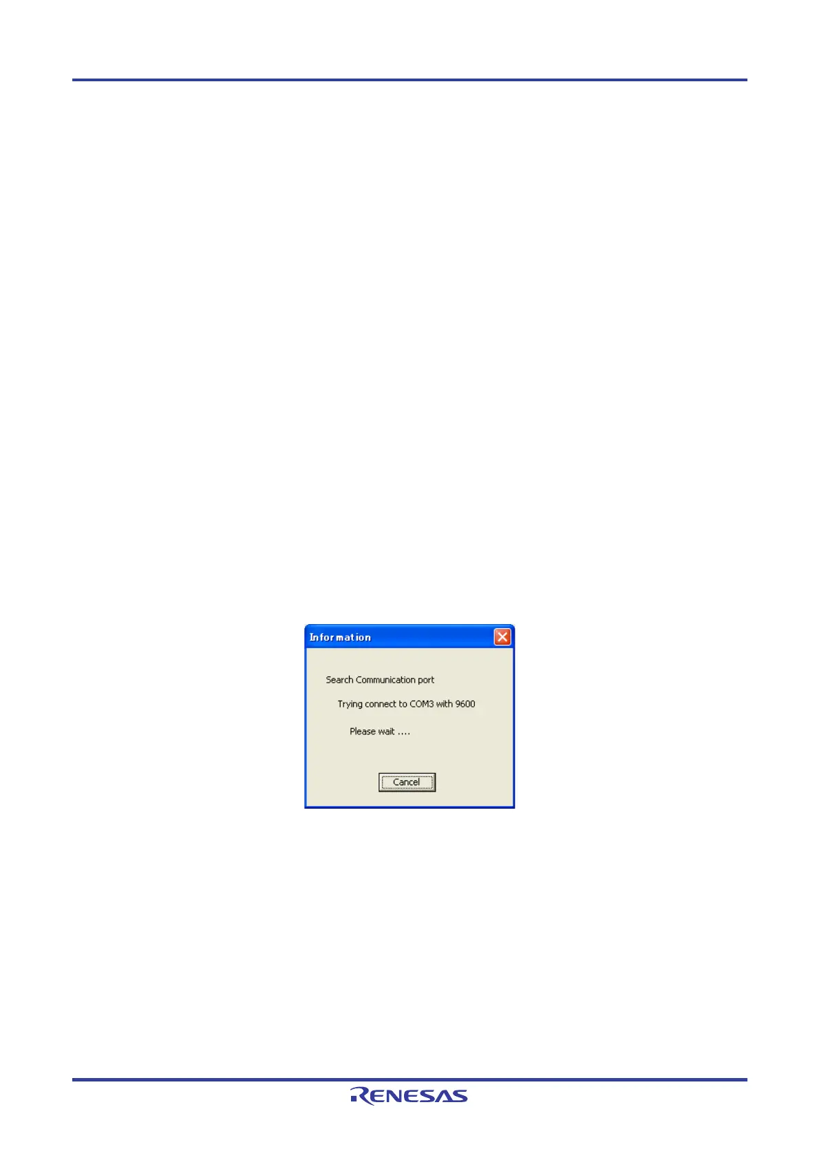
(5) Startup of programming GUI
<1> Click the Start menu, “All Programs”, point to “NEC Electronics Tools”, “Latest Version”, and then select
“PG-FP5 Vx.xx” to start the Programming GUI. The valid communication modes are automatically
detected in the order of the USB, and then the serial interface.
Figure 5-1. Connection Between Programming GUI and FP5