PG-FP5 CHAPTER 4 PROGRAMMING GUI USAGE
R20UT0008EJ0400 Rev. 4.00 Page 88 of 240
Jul 15, 2010
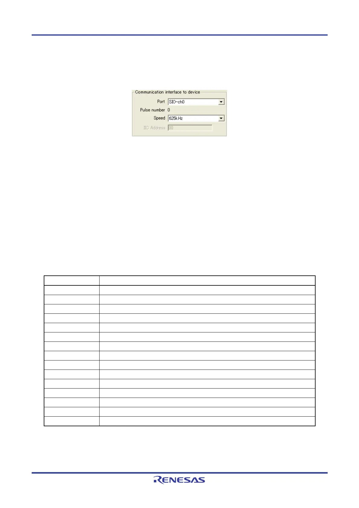
<1> [Communication interface to device] area
In this area, select the channel and speed for communication between the FP5 and target device.
Figure 4-61. [Communication interface to device] Area
[Port] list
Select the mode of communication between the FP5 and target device. The communication mode is determined
by the number of V
PP output from the FP5 or the FLMD0
Note
pulse count. The selectable communication mode
differs depending on the target device. Refer to the user’s manual of the target device used and select a mode.
With some devices, the channel number may start from 1. In this case, the corresponding number is shifted, for
example, ch0 shown in the screen corresponds to ch1 of the device, and the displayed channel number must be
shifted accordingly.
Note FLMD0 in a single-power-supply flash memory microcontroller, or FLMD1 in a two-power-supply flash memory
microcontroller.
Remark For the available communication channel, refer to the user’s manual of the target device, based on the pulse
count displayed for “Pulse number”.
Table 4-2. Channels for Communication Between FP5 and Target Device (1/2)
Item on Screen Description
SIO-ch0 SIO (3-wire clocked communication port) channel 0
Note
SIO-ch1 SIO (3-wire clocked communication port) channel 1
SIO-ch2 SIO (3-wire clocked communication port) channel 2
SIO-H/S SIO (3-wire clocked communication port, with handshake pin)
IIC-ch0 I
2
C channel 0
IIC-ch1 I
2
C channel 1
IIC-ch2 I
2
C channel 2
IIC-ch3 I
2
C channel 3
UART-ch0 UART (asynchronous communication port) channel 0
UART-ch1 UART (asynchronous communication port) channel 1
UART-ch2 UART (asynchronous communication port) channel 2
UART-ch3
UART (asynchronous communication port) channel 3
Port-ch0 Port (pseudo 3-wire) A
Port-ch1 Port (pseudo 3-wire) B
Port-ch2 Port (pseudo 3-wire) C
Note This might be "3-wire clocked communication port, with handshake" depending on the target device.