PG-FP5 CHAPTER 4 PROGRAMMING GUI USAGE
R20UT0008EJ0400 Rev. 4.00 Page 90 of 240
Jul 15, 2010
• 100k Baud
<When Port-ch0, Port-ch1 or Port-ch2 is selected>
• 100 Hz
• 200 Hz
• 300 Hz
• 400 Hz
• 500 Hz
• 600 Hz
• 800 Hz
• 1000 Hz
• 1200 Hz
• 1500 Hz
• 2000 Hz
[IIC Address] area
If I
2
C is selected as the communication channel, input a hexadecimal number as a slave address of the target
device. The valid input range is 8 to 77h. Do not input a unit. The slave address can be any value in the above
range but must not be the same as the slave address of another target device on the I
2
C. This field is not
available if the I
2
C port is not selected.
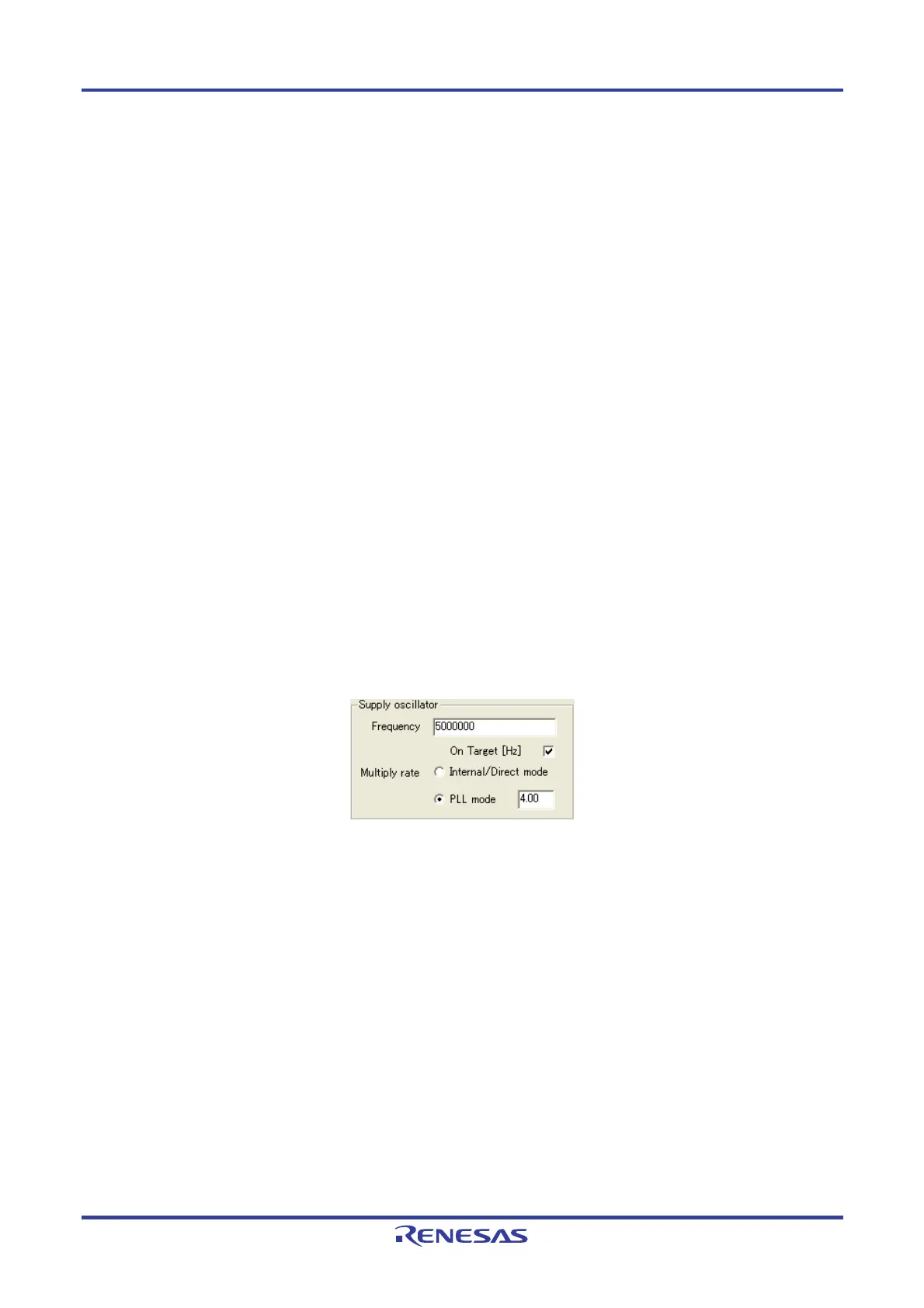
<2> [Supply oscillator] area
Set the clock to be supplied to the target device.
Figure 4-62. [Supply oscillator] Area
[Frequency] text box
Set the oscillation frequency of the clock supplied to the target device. When using the clock mounted on the
target system ([On Target] check box selected), input its oscillation frequency. When using the clock on the FP5
side ([On Target] check box cleared), input one of the following.
• 1 MHz
• 2 MHz
• 4 MHz
• 5 MHz
• 6 MHz
• 8 MHz
• 9 MHz
• 10 MHz
• 12 MHz
• 16 MHz
• 20 MHz
Remark For the selectable frequency, refer to the user's manual for the device used.