100
26. Annex
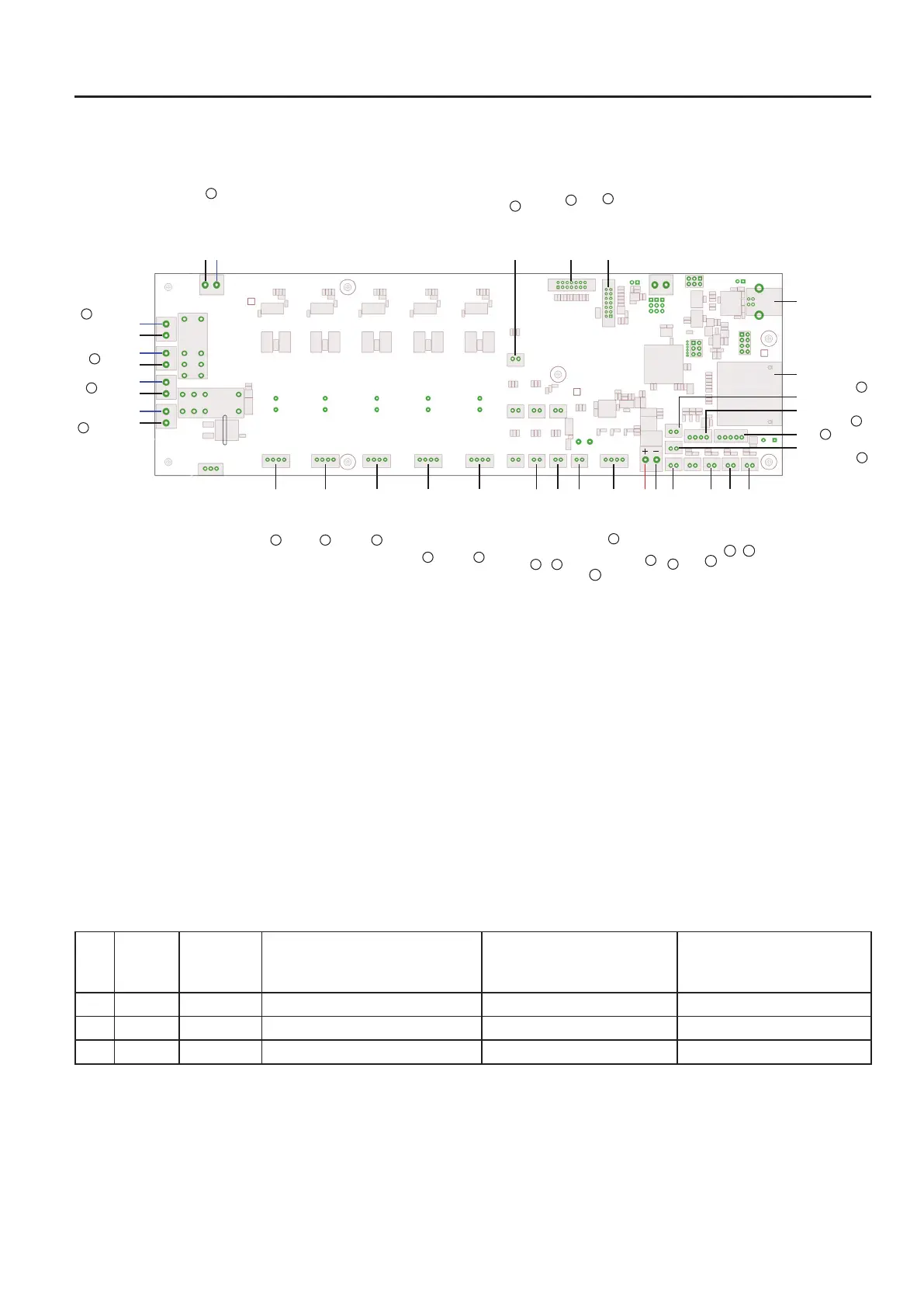
a) Wiring plan
Connection plan of the main PCB
Abbreviations used:
230 V SWITCH = This is where the cable from the low-power device combination socket is connected.
bl = The respective blue line is connected here
sw = The respective black line is connected here
EXT.=extruder
DMS = elongation measuring strip
LIMITSWITCHZ-MAX=LimitswitchinstalledatthebottomoftheY-plate
LIMITSWITCHZ-MIN=LimitswitchinstalledatthebottomoftheX-plate(lightbarrier)
The number designations at the lines correspond to the cable marks at the individual cables.
Overview of all lines and connections
Line Length Connection
main
PCB
Pin number plug/main PCB
(all
pins on white plugs; colour based
on pin1)
Component Pin number plug/component
(all pins on plugs; colour based
on pin1)
1 735 mm X11 4pin green/yellow/white/brown MotorX 4pin yellow/green/brown/white
2 840 mm X12 4pin green/yellow/white/brown MotorY 4pin yellow/green/brown/white
3 380 mm X16 4pin green/yellow/white/brown Motor Z 4pin yellow/green/brown/white
X36
X13
X14
X5X6X9X35
X7X15
X11 X18X17X16X12
X1
X43
X24X4X8X42
X44 X19X10
X45
X46
X34
X33
X2
X21
X23
X32
X30
X31
X39
X38
X37
X40
X41
MOTOR X
LIMIT SWITCH Y
LIMIT SWITCH
Z-MAX
LIMIT SWITCH
Z-MIN
LIMIT SWITCH X
MOTOR EXT.0
MOTOR Z
MOTOR Y
MOTOR EXT.1
HEATING EXT.0
HEATING EXT.1
FAN EXTRUDER
ADDITIONAL BOARD
RGB-LED
24 V/DC INPUT
TEMP.
PRINT PLATE
TEMP. EXT.0
TEMP. EXT.1
POWER PLUG
HEATING
PRINT
PLATE
POWER
SUPPLY
EMERGENCY
OFF SWITCH
230V SWITCH
CASE FAN
KEYBOARD
LC-DISPLAY
USB
SD
DMS
bl
sw
bl
sw
bl
sw
bl
sw
sw
rot
bl
sw
28
32
4 4
44
1 2 3
5
13
7
9
6
8
1011
12
15
14
29
23
24
25
26
27