15
b)Installationofthelamentholder
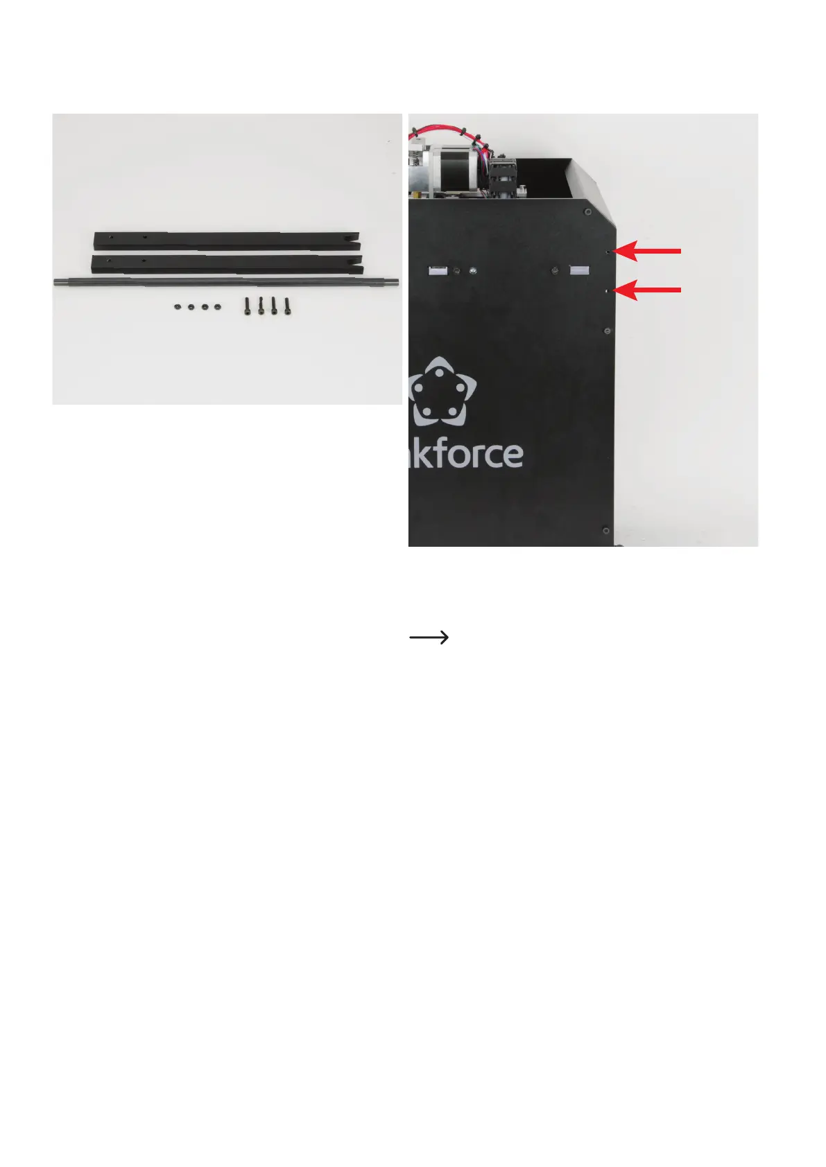
Assemblyofthelamentholder
2xlamentholderpart
1xshaftforlamentholder
4 x nut M4 (black)
4 x cylinder head screw M4x20 (black)
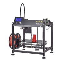
Thetwolamentholderpartsareinstalledononesideoftheprinter
eachinthetwoupperrearholes(seearrowsinthegure).
Ifyouhavepurchasedthenisheddevice,the4cylinder-headscrews
and nuts will be enclosed.
Please note! The two lament holder parts must be in-
stalled so that they end with the rear edge of the respective
side part.