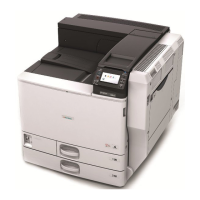
Rear and left view
CFE022
2
3
1
88
99
55
66
77
1010
1111
4
1. Ventilation holes
Prevent the machine from overheating.
2. Rear cover
Open this cover to remove misfed paper.
3. Rear cover lever
Pull up on this lever to open the rear cover.
4. Power connector
Connect the power cord to the machine here. Insert the other end of the cable into a nearby wall outlet.
5. SD card slots
There are two SD card slots. Install SD cards here.
6. USB 2.0 [Type B] port
Connect the USB2.0 [Type B] interface cable here.
7. USB Host Interface
Connect the USB interface cable here.
Use this interface to connect the machine to a card authentication device.
8. 10BASE-T/100BASE-TX port
Connect the 10BASE-T or 100BASE-TX cable here.
9. Optional board slot
Install an optional board in this slot.
10. External telephone connector (Standard for type 2, and optional for types 1 and 3)
Connect an external telephone here.
11. G3 interface unit connector (Standard for type 2, and optional for types 1 and 3)
Connect a G3 line here.
Guide to Components
51
 Loading...