EasyManua.ls Logo

Ricoh DD 4450 Service Manual

Ricoh DD 4450
269 pages
To Next Page IconTo Next Page
Page #1 background imageLoading...
Page #1 background image
C279
SERVICE MANUAL

Table of Contents

Question and Answer IconNeed help?

Do you have a question about the Ricoh DD 4450 and is the answer not in the manual?

Ricoh DD 4450 Specifications

General IconGeneral
TypeDigital Duplicator
Print Speed130 ppm
OriginalsSheet
Scanning SpeedNot Available
Paper Capacity1, 000 sheets
ConnectivityUSB
Weight102 kg
Print paper sizeA3
Print paper weight46 to 210 g/m²
Image modesPhoto
Image positionVertical: ±10 mm, Horizontal: ±10 mm
Reduction ratios87%
Enlargement ratios141%
Power sourceAC 220-240V, 50/60Hz
Power consumptionMaximum: 300 W

Summary

C279 Service Manual Overview

Service Manual Warning

Product Information

Product Specifications

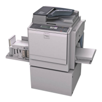
Details on main frame, paper sizes, software, and optional equipment.

Installation Procedure

Installation Requirements

Specifies optimal environmental conditions and power connection requirements.

Optimal Environmental Conditions

Defines temperature and humidity ranges for machine installation.

Machine Installation Steps

Step-by-step guide for installing the main machine and its accessories.

Power Connection Guidelines

Ensures secure and proper power cord connection to the source.

Machine Installation Steps

Step-by-Step Machine Installation

Detailed instructions for unpacking, mounting, and securing the machine.

Preventive Maintenance Overview

Important Safety Notices

Customer Engineer Responsibilities

Maintenance must be performed by trained and certified customer engineers.

Power Safety Precautions

Installation and Adjustment Safety

Ensuring proper operation after installation/adjustment and avoiding hazardous contact.

During Maintenance Safety

General Maintenance Safety

Switch off power and disconnect before maintenance procedures.

Safety Device Handling

Never remove or defeat safety devices; ensure proper replacement and testing.

Power Plug and Cord Safety

Machine Safety Instructions

Prevention of Physical Injury

Unplugging power, avoiding hot parts, and keeping away from flammables.

Health Safety Precautions

First aid for ink exposure to eyes or ingestion.

Product Information Section

Product Overview

Component Layout Diagram

Diagram showing the physical components and their numbering.

Electrical Component Layout Diagram

Machine Boards and Functions

Machine Motors and Functions

Machine Sensors and Functions

Drive Layout Diagram

Installation Procedure Section

Peripheral Power Socket Usage

Step-by-Step Machine Installation

Machine Installation: Power On and Test Copy

Network Controller Installation: Board Preparation

Preventive Maintenance Section

Appendix: Preventive Maintenance (PM) Tables

Preventive Maintenance Schedule

Details maintenance intervals (6M, 1Y, Print Counter, Any time) and actions (C, R, L).

Replacement and Adjustment Section

Replacement and Adjustment Procedures

Pre-Replacement and Adjustment Procedures

Turn off power, print jobs, and disconnect cables before starting.

Special Tools Required for Service

Image Adjustment Procedures

SP6-10 Master Writing Speed Adjustment

Procedure to adjust master writing speed for image quality.

SP6-100 to 107 Paper Registration Adjustment

Adjusts paper registration for accurate image placement.

SP6-01, 6-02 Main Scan Position Adjustment

Adjusts main scan position for platen and ADF modes.

SP6-05, 6-06 Scanning Speed Adjustment

Adjusts scanning speed for platen and ADF modes.

SP6-20 Standard White Execution (Auto Calibration)

Performs auto calibration after replacing specific components.

SP6-03, 6-04 Scanning Start Position Adjustment

Adjusts scan start position for platen and ADF modes.

Covers and Boards Removal/Installation

Front Cover and Operation Panel Removal

Front Door Safety Switch Replacement

MPU Replacement Procedure

MPU Replacement: NVRAM and Image Adjustments

PSU Replacement Procedure

Instructions for replacing the Power Supply Unit (PSU).

PSU Replacement: Thermal Head Voltage Adjustment

Scanner Unit Maintenance

Exposure Glass Replacement

Original Length Sensors Replacement

Exposure Lamp Replacement

Reassembling the Front Scanner Wire

Scanner Motor Replacement

Sensor Board Unit (SBU) Replacement

Scanner HP Sensor Replacement

Platen Cover Sensor Replacement

Front Scanner Wire Replacement

Reinstalling the Front Scanner Wire

Rear Scanner Wire Replacement

Master Eject Unit Maintenance

Master Eject Safety Switch Replacement

Eject Box Set Switch Replacement

Master Feed Maintenance

Thermal Head Replacement

Thermal Head Installation Procedure

Duct Plate Sensor and Motor Replacement

Duct Plate Motor Replacement

Duct Jam Sensor Adjustment

Master Edge Sensor Adjustment

2nd Drum Master Sensor Adjustment

Master End Sensor Adjustment

Thermal Head Voltage Adjustment

Paper Feed Maintenance

Paper Separation Pressure Adjustment

Paper Width Detection Board Installation

Printing Maintenance

Press Roller Release Lever Adjustment

Printing Pressure Adjustment

Drum Maintenance

Cloth Screen Installation Procedure

Clamper and Metal Screen Maintenance

Metal Screen Installation Procedure

Mylar Seal Installation

Ink Pump Adjustment Procedure

Ink Roller Unit and One-Way Clutch Maintenance

Idling Roller Motor and HP Sensor Maintenance

Doctor Roller Gap Adjustment

Ink Detection Adjustment

Main Motor Pulley Position Adjustment

Main Drive Timing Belt Adjustment

Paper Delivery Maintenance

Fan Motor and Exit Sensor Replacement

Exit Pawl Adjustment (Timing)

Exit Pawl Clearance Adjustment

Air Pump Adjustment

Fuse, LED, VR, DIP-SW, and TP Tables

Blown Fuse Conditions and Symptoms

Lists fuse numbers, ratings, and associated symptoms for the PSU.

Variable Resistors (VRs) for Adjustment

Lists VRs for MPU, PSU, and Ink detection board with their adjustment functions.

Test Points for MPU and PSU

Identifies test points on MPU and PSU for voltage measurements.

System Maintenance Reference Section

System Maintenance Reference

Service Program Mode Overview

Introduction to using Service Program (SP) modes for maintenance.

Using Service Program Modes

Instructions on how to access and utilize SP modes for data checks and adjustments.

Selecting a Program Number in SP Mode

Troubleshooting Guide

Firmware Update Procedures

Firmware Update: Before You Begin

Preparing Firmware for Download

Firmware Download: Data Transfer and Verification

Downloading Main/ADF Firmware

Downloading FV-LT Firmware

FV-LT Firmware Download: Completion and Verification

Electrical Component Defects and Jams

Sensor Malfunctions and Symptoms

Details sensor conditions (open/shorted) and their corresponding symptoms/error codes.

Sensor Malfunctions and Symptoms

More Sensor Malfunctions and Symptoms

Details malfunctions for 2nd Feed, Master Eject, Clamper, Table Lower, and Platen Cover sensors.

More Sensor Malfunctions and Symptoms

Further Sensor Malfunctions and Symptoms

Details malfunctions for Scanner HP, Original Length/Width, Master Set Cover, Master End, and Paper Height sensors.

Further Sensor Malfunctions and Symptoms

Additional Sensor Malfunctions and Symptoms

Details malfunctions for Registration, Paper End, Cutter HP, Paper Size, and Paper Length sensors.

Additional Sensor Malfunctions and Symptoms

Advanced Sensor Malfunctions and Symptoms

Details malfunctions for Ink Idling Roller, Printing Pressure HP, 2nd Drum Master, Duct Jam, Duct Plate HP, and Master Edge sensors.

Advanced Sensor Malfunctions and Symptoms

ADF Sensor Malfunctions and Symptoms

ADF Sensor Malfunctions and Symptoms

Details malfunctions for ADF Org Exit, Feed Cover, and ADF Lift Up sensors.

Switch Malfunctions and Symptoms

Interlock Switch Malfunctions and Symptoms

Details malfunctions for the Interlock Switch and its conditions.

Interlock Switch Malfunctions and Symptoms

Power Supply Unit (PSU) Issues

Controller Component Errors

Energy Saving Features

Energy Save Mode

Explains energy saving modes and timer settings for energy conservation.

Appendix: General Specifications

Appendix: Specifications Section

Main Frame Specifications

Supported Paper Sizes (Europe/Asia)

Supported Paper Sizes (North America)

Appendix: Preventive Maintenance Tables

Appendix: Service Call Conditions

Service Call Error Codes and Causes

Lists error codes (E-00 to E-09) and their possible causes.

Service Call Error Codes and Causes

More Service Call Error Codes and Causes

Lists error codes (E-10 to E-22) and their possible causes.

More Service Call Error Codes and Causes

Further Service Call Error Codes and Causes

Lists error codes (E-23 to E-50) and their possible causes.

Program Download Error Codes

Lists error codes related to firmware download failures.

Appendix: Service Program Mode Tables

Service Program (SP) Table Overview

Explains how SP tables are read and the meaning of categories and SP names.

Service Program Mode Usage

Instructions on how to access and utilize SP modes for data checks and adjustments.

SP Mode Tables

Provides detailed tables for various SP modes (1X, 2X, 3X, 4X).
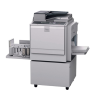
1X SP Mode Table: Copy Data and Counters

1X SP Mode Table: Jam Data and Firmware

1X SP Mode Table: SBU Error Location

1X SP Mode Table: SBU Level Error Location

2X SP Mode Table: Basic Settings

2X SP Mode Table: Ink, Paper, and Drum Sensors

2X SP Mode Table: Ink, Paper, and Drum Settings

2X SP Mode Table: Idling and Re-Feeding Settings

2X SP Mode Table: Print Pressure and Speed Settings

2X SP Mode Table: Thermal Head (T/H) Control

2X SP Mode Table: Thermal Head (T/H) Energy Control

2X SP Mode Table: T/H Swinging and Scanning Adjustments

2X SP Mode Table: Paper Table and Master Making Settings

2X SP Mode Table: Drum Master and Registration Settings

3X SP Mode Table: System Settings

3X SP Mode Table: Installation Date and Key Settings

4X SP Mode Table: Input Mode (Sensor Checks)

4X SP Mode Table: Drum and Paper Sensors

4X SP Mode Table: Additional Sensors and Signals

5X SP Mode Table: Output Mode (Motor Checks)

5X SP Mode Table: Motor Speed and Pressure Controls

5X SP Mode Table: Fan, Delivery, and Counter Controls

5X SP Mode Table: Printer Controls and ADF Functions

6X SP Mode Table: Adjustment (Sensor Thresholds)

6X SP Mode Table: Scan Adjustments and Skew Correction

6X SP Mode Table: Master Writing Speed and Registration

6X SP Mode Table: Paper Registration and White Execution

6X SP Mode Table: Master Density and MTF Filter Settings

6X SP Mode Table: Ink Detection and Sensor Voltages

6X SP Mode Table: Master Returning and Pressure Settings (Low Temp)

6X SP Mode Table: Pressure Settings (Normal/High Temp) and Gain Adjustments

6X SP Mode Table: Digital Gain and Paper Registration Adjustments

6X SP Mode Table: Paper Registration Steps and Skip Settings

6X SP Mode Table: Paper Middle Bulge Adjustments

6X SP Mode Table: Image Adjustment (Doubled/Blurred Images)

6X SP Mode Table: Paper Front Bulge Adjustments

6X SP Mode Table: Paper Registration (A4 Drum) Adjustments

6X SP Mode Table: Original Length/Width and Lamp ON Timing

7X SP Mode Table: Memory Clear and Protect Code

8X SP Mode Table: System Test and Firmware Download

8X SP Mode Table: Security Off and Paper Feed Settings

8X SP Mode Table: Print Mode and Indicator Checks

9X SP Mode Table: Print Controller and Data Output

9X SP Mode Table: Service Summary and Printer Settings

Related product manuals