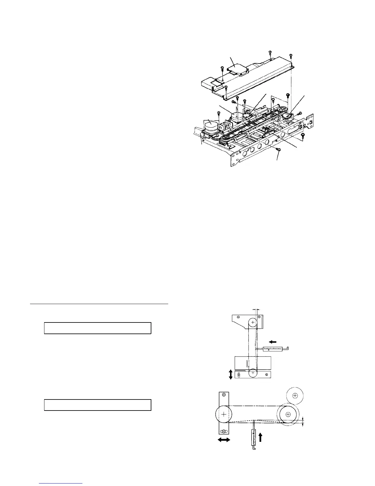
2.10.18 Replacing parts in the duplex tray unit
This procedure explains how to remove or replace the
following parts:
• The jogger and back fence motors and their
timing belts.
• The jogger and back fence home position
sensors.
1. Remove the duplex tray unit from the copier.
2. Reverse the unit and remove the motor cover (4
screws).
3. Remove or replace the jogger motor and back
fence motor (2 screws each).
4. Remove the belt fixing screws (one each for the
jogger and back fence timing belts).
5. Mark off the position and remove the belt tension
brackets (2 gold screws each).
6. Replace the timing belts.
CAUTION
• The belt tension brackets should be in the
marked positions.
• Before installing the back fence motor
timing belt, the back fence should be
smooth enough to drop by its weight when
the duplex tray unit is stood up with the
motors at the top.
• The side fences should not come up above
the tray bottom plate.
7. Replace the jogger and back fence home position
sensors (2 screws each).
8. Reassemble in the reverse order.
Belt tension standards
• Back fence belt
3 mm deflection at 20 ± 10 g pressure.
• Side fence (jogger) belt
6.5 mm deflection at 20 ± 10 g pressure.
Motor cover
Jogger HP
sensor
Belt tension
bracket (jogger)
Belt tension
bracket (back
fence)
Belt fixing screw
Side fence
Jogger motor
Back fence
motor
3 mm
20 ± 10 g
20 ± 10 g
6.5 mm



 To Next Page