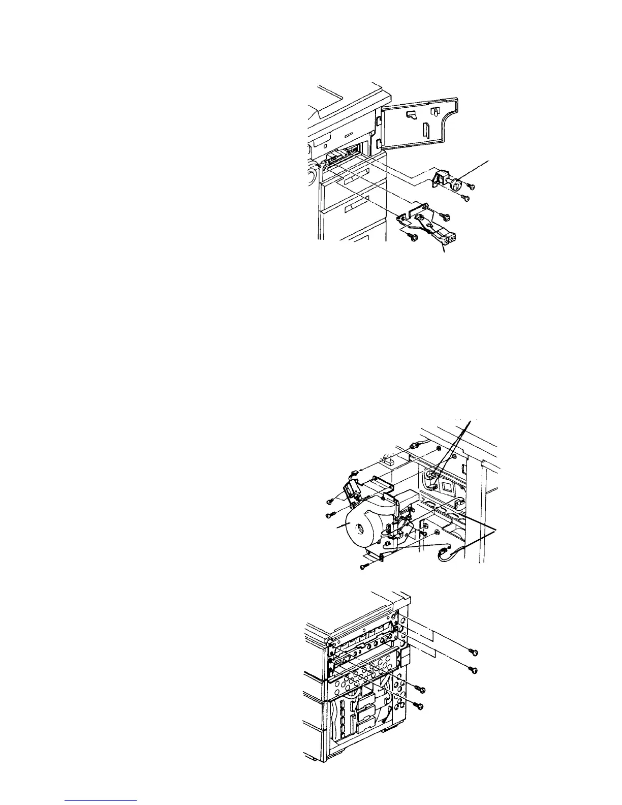
2.10.19 Removing the duplex/exit unit
WARNING
Due to the weight of the duplex/exit unit, this
procedure needs two operators.
1. Turn off the main switch. If peripherals are
installed, remove them from the copier.
2. Remove the copier’s right cover (2 screws).
3. If the machine is equipped with the LCT, remove
the horizontal transport unit as follows:
1) Remove the lock lever and knob assemblies.
2) Disconnect the connector at the right side of the
horizontal transport unit from the main body.
3) Remove two screws and pull out the unit from
the right side.
CAUTION
• Be careful not to damage the paper guide
plates when pulling out or installing the unit.
• When reinstalling the lock lever assembly,
be sure that the assembly completely locks
the upper guide plates and that the lock
lever bracket pushes down the upper left
paper guide plate of the unit. Otherwise,
paper misfeeds may occur there.
4. Remove the rear right cover (2 screws).
5. Remove the duplex blower unit (3 connectors and
4 screws).
6. Disconnect the two connectors behind the duplex
blower unit.
7. Raise the ADF and remove the SADF transport
plate (one stepped screw on the rear and one
plated screw on the front).
8. Open the copy tray.
9. Remove the eight duplex/exit unit fixing screws
from the right side of the copier.
10. Slide the duplex/exit unit to the right side. Two
operators are required for this step due to the
weight of the unit.
11. Lay down the unit.
Knob assembly
Lock lever assembly
Connectors
Duplex
blower unit
Blower
connectors



 To Next Page