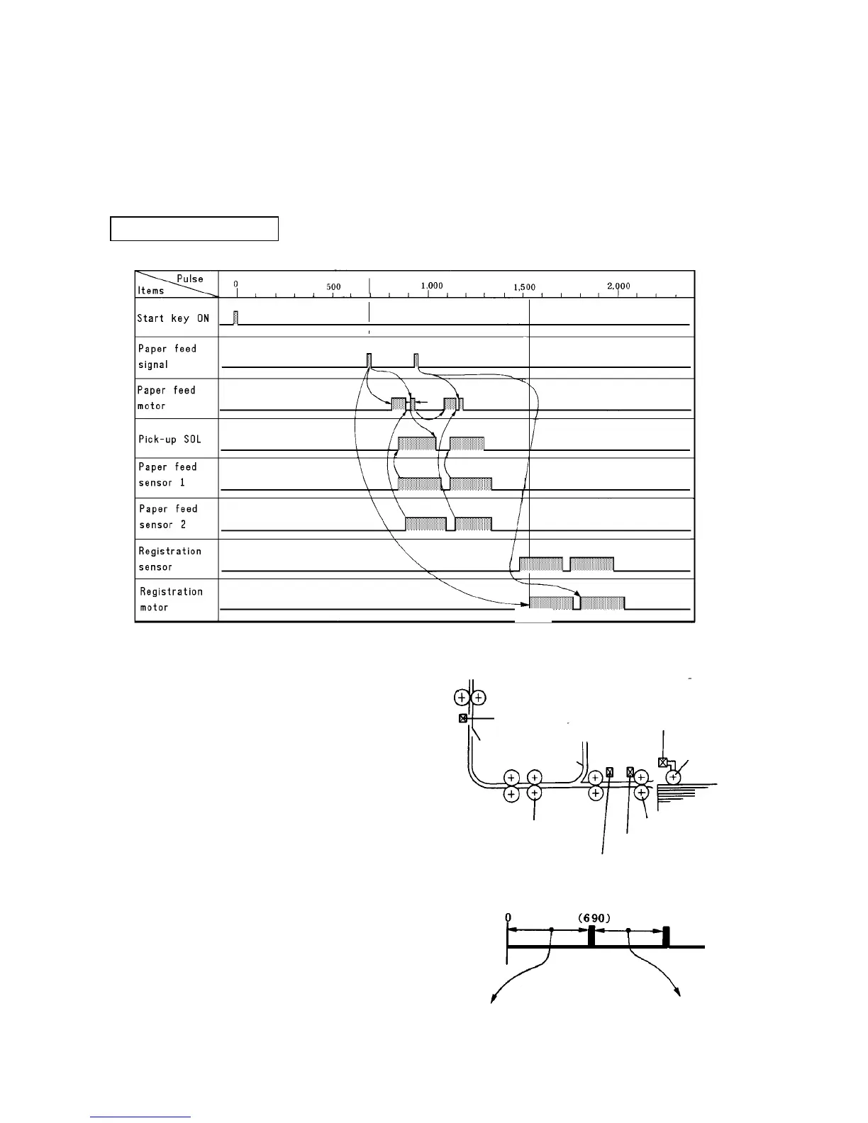
2.1.12 Timing chart
The conditions in effect for the chart below are as
follows:
• A4 size paper
• 2 continuous copies
• Paper feed from tray 1
• Platen cover mode
Pulse conversion is:
1 pulse = 2.34 msec = 1 mm
Description
❈1 In the platen cover mode, pulse counting starts from
when the start key is ON, but in the ADF mode, the
count starts 3.5 sec after ON.
❈2 The paper feed signal is generated from the main
control board.
❈1
❈6
❈5
❈3
❈4
(690P)❈2
1.505
Registration sensor
Pick-up SOL
Pick-up roller
3rd paper tray
Reverse roller
Paper feed sensor 1
Paper feed sensor 2
Grip roller
The first paper feed signal after start
key ON varies for each paper feed
station and with paper size to match the
imaging position of the photoconductor
(tray 1 is earlier than 3).
Paper feed signal after
the second feed varies
according to paper
size.