2.2.5 Shield mechanism
The image position made on the OPC differs by paper
size. Left and right shields control the exposure area.
The shield unit has right and left shield screens that can
be moved separately left and right by the shield motors.
The shield motors are stepping motors and are operated
by the mirror/lens motor drive board.
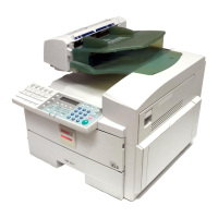
Shield screen drive
When the start key is pressed, the shield motors turn to
position the shields to match paper size and
magnification.
The motors separately move the right and left shield
screens through gears and timing belts. The home
position of each shield screen is detected by a shield HP
sensor.
Setting the shield area
The shield area of the right and left shield screens is
determined by the paper size and magnification. The
right and left shield motors are driven independently by
pulses from the mirror/lens motor drive board.
The shield home position is the A4 full-size position, and
transfers to other specified positions are done by using
this position as reference.
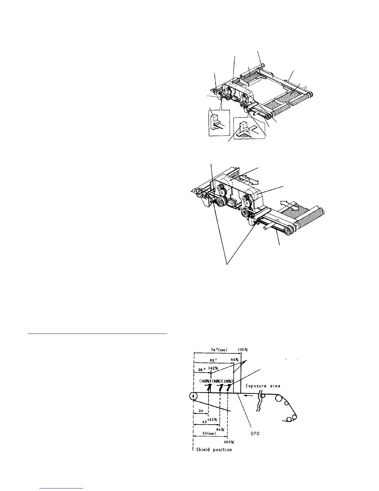
Left shield screen
The shield area of the left shield screen is determined by
the magnification data, regardless of paper size. This is
because the exposure area on the OPC varies with the
shift of the lens and mirror during magnification.
The figure on the right shows the left shield screen stop
position for several magnification values.
When the exposure area is changed, the image position
on the OPC also changes (48 mm maximum), but the
rotation of the OPC is constant and the seam on the
OPC limits the image area. The image area on the OPC
is matched by varying flash timing.
Timing belt
Timing belt
Right shield
(Right side)
Right shield motor
Timing belt
Timing pulley
Shield HP sensor
Timing pulley
Shield HP sensor
Timing belt
Left
shield
Left shield motor
Timing belt
Shield motor
Shield motor
Timing belt
Shield connector bracket
Left shield screen shield area
Left shield screen
Position of leading edge of image