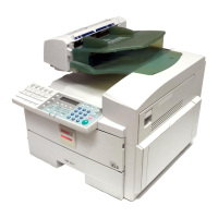
4. Remove the shielding cover for the LCT harness
and the rear right cover from the copier.
Remove one screw to remove the connector cover.
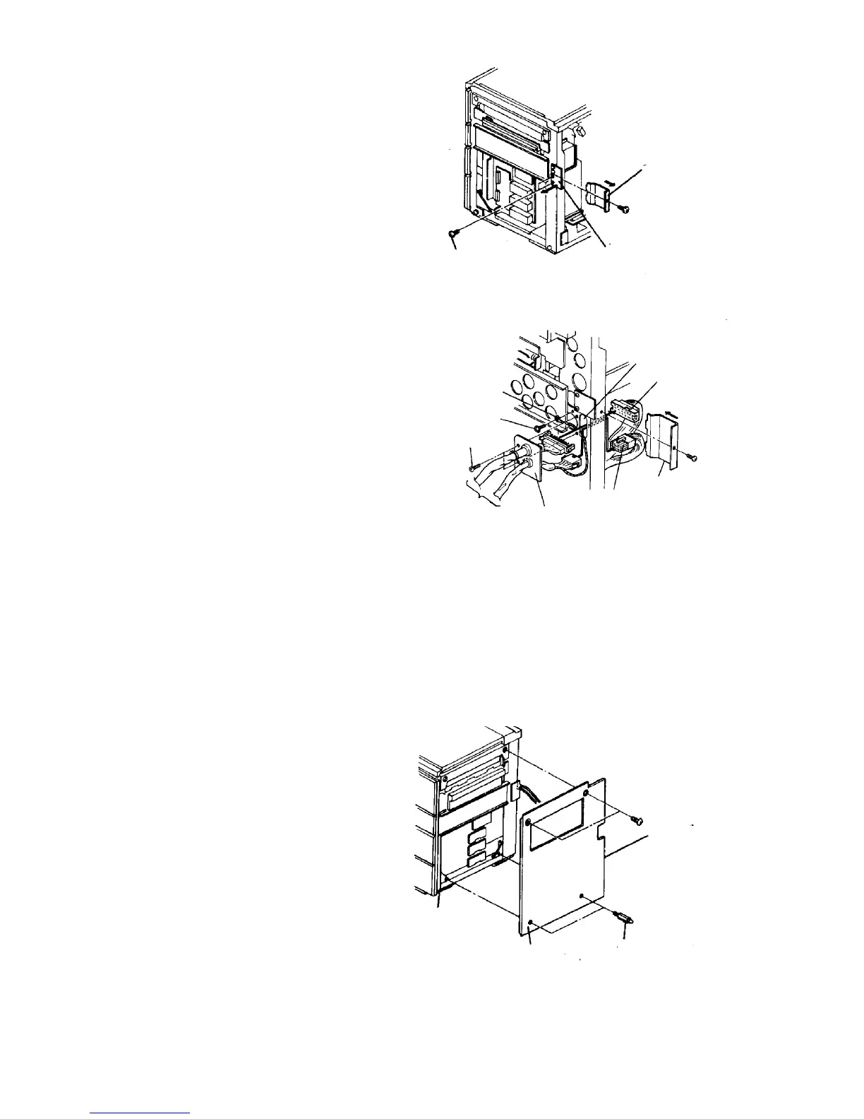
5. Pass the LCT power and signal harnesses through
the copier frame hole, and fix the harness fixing
bracket with the two truss screws removed above.
6. Connect the 15P and 34P connectors respectively.
NOTE
The maximum load current of the LCT is 0.95 A.
7. Take the protective earth wire, feed it through
holes provided as shown, and fix it with the
grounding screw (accessory).
8. Fit the connector cover and copier rear right cover
if the finisher will not be installed.
9. Set the two wire saddles (accessories) in the hole
of the LCT rear cover, and put the power cord from
the LCT in it.
NOTE
One of the wire saddles is for the harness from the
finisher.
10. Remove two blind caps from the copier right cover,
and reinstall the right cover. Then, install the
docking pins to the copier base.
Connector cover
Shielding cover for
LCT (lower side)
M4 x 6 truss screws (2)
Frame hole
34P connector
Connector cover
15P connector
Harness
fixing
bracket
LCT power and
signal harnesses
Truss screw
Grounding screw
Protective earth wire
Right cover
Docking pin
Main body