Chapter 4 To Set the Sample System RIGOL
MSO7000/DS7000 User Guide 4-3
channels. The definitions of A, B, C, and D are shown in the above figure. The phase
deviation angle is obtained, that is:
=arcsin(A/B) or arcsin(C/D)
If the principal axis of the ellipse is within Quadrant I and III, the phase deviation
angle obtained should be within Quadrant I and IV, namely within (0 to π/2) or (3π/2
to 2π). If the principal axis of the ellipse is within Quadrant II and IV, the phase
deviation angle obtained should be within Quadrant II and III, namely within (π/2 to
π) or (π to 3π/2).
The XY function can be used to measure the phase deviation occurred when the
signal under test passes through a circuit network. Connect the oscilloscope to the
circuit to monitor the input and output signals of the circuit.
Application example: measures the phase deviation between the input signals of
two channels.
Use Lissajous method
1. Connect one sine signal to CH1, and then connect another sine signal (with the
same frequency and amplitude as the previous one but a 90° phase deviation
from the previous one) to CH2.
2. Press AUTO, after you select "XY" mode, rotate the Horizontal SCALE to
adjust the sample rate properly to obtain a better view of Lissajous graph for
observation and measurement.
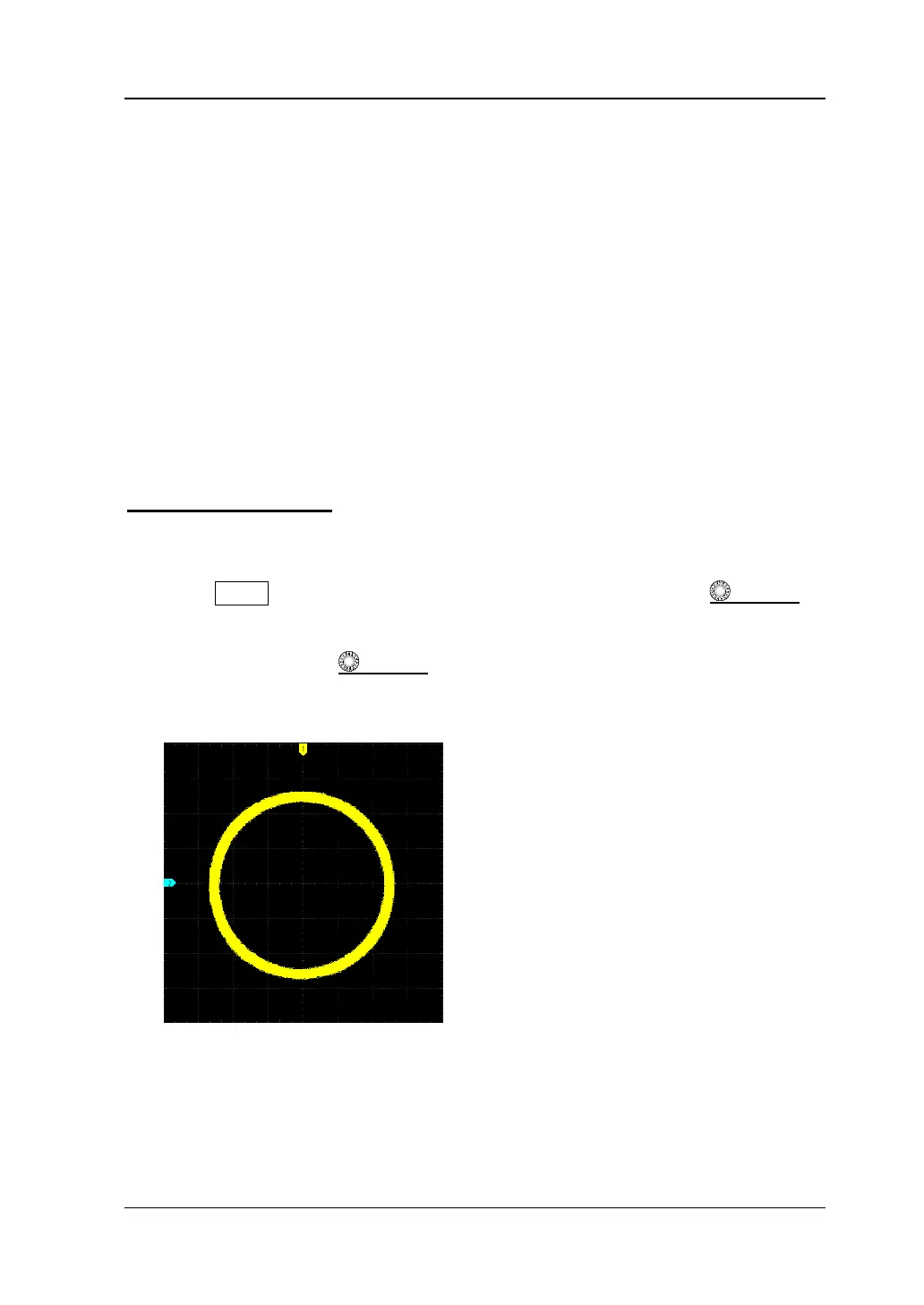
3. Rotate the Vertical SCALE knob that corresponds to CH1 and CH2
respectively to make the signals easy to observe. Then, a circle, as shown in the
figure below, should be displayed.
4. Observe the measurement result shown in the figure above. According to the
measurement schematic diagram of the phase deviation (as shown in Figure
4-1), A/B(C/D)=1. Thus, the phase deviation angle of the two channel input
signals is =arcsin1=90°.