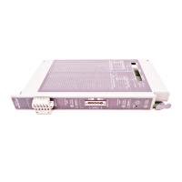
Do you have a question about the Rockwell Automation 1769-IF4 and is the answer not in the manual?
Describes the 1769-IF4/-IF8 analog input and 1769-OF2/-OF8C/-OF8V analog output modules and their capabilities.
Explains the operational sequence of the modules, including power-up checks, configuration, and data conversion processes.
Details the maximum current draw for the modules from the system or external power supply.
Emphasizes the critical safety procedure of removing power before inserting or removing modules to prevent arcs and injury.
Provides step-by-step instructions for safely replacing a module while the system is mounted.
Provides general wiring considerations and specific guidelines for analog input and output modules.
Explains the memory map and addressing scheme for the 1769-IF4 analog input module.
Details the input data file structure for accessing analog input module read data and status bits.
Describes the meaning of input data values, general status bits, over-range, and under-range flag bits.
Details the bit fields within channel configuration words that determine channel operation and settings.
Illustrates the memory map for the 1769-OF2, showing output, input, and configuration tables.
Details the output data file structure, containing commanded analog output data for channels.
Details bit fields in configuration words that determine how corresponding channels operate and their settings.
Describes configuration for selecting individual fault mode behavior for analog output channels.
Lists general specifications including dimensions, temperature, humidity, altitude, vibration, shock, and power supply ratings.
Provides detailed specifications for the 1769-IF4 analog input module, including ranges, resolution, and accuracy.
Details specifications for the 1769-IF8 analog input module, covering ranges, resolution, accuracy, and electrical characteristics.
Lists detailed specifications for the 1769-OF2 analog output module, including ranges, resolution, and accuracy.
Provides detailed specifications for the 1769-OF8C analog output module, covering ranges, accuracy, and electrical data.
Details specifications for the 1769-OF8V analog output module, including ranges, accuracy, and electrical characteristics.
| Brand | Rockwell Automation |
|---|---|
| Model | 1769-IF4 |
| Category | I/O Systems |
| Language | English |


