1 Publication 1769-UM002B-EN-P - July 2005
Appendix
B
Module Addressing and Configuration with
MicroLogix 1500
This chapter examines the analog modules’ addressing scheme and describes
module configuration using RSLogix 500 and MicroLogix 1500.
Input Module Addressing
In the following example, the 1769-IF4 is used. Detailed information on the
input image table can be found in 1769-IF4 Input Data File on page 3-2.
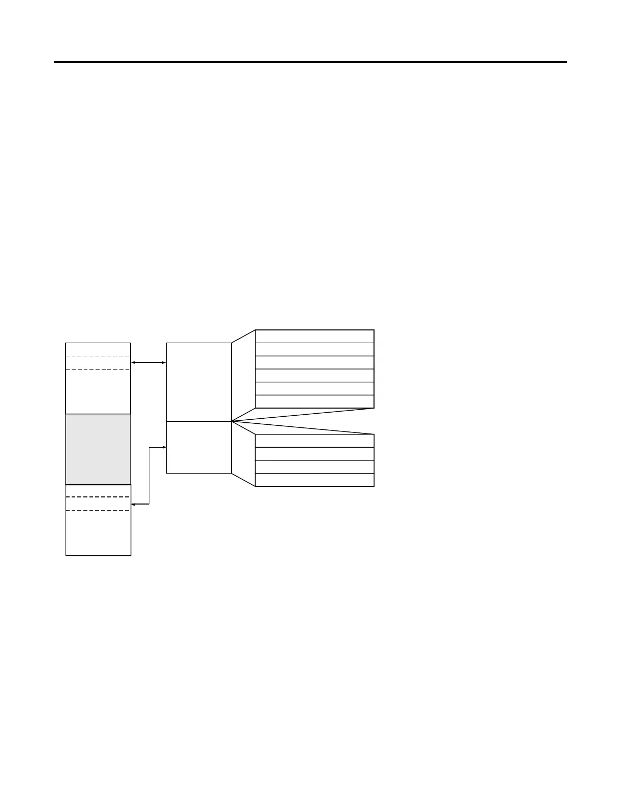
Figure B.1 1769-IF4 Memory Map Including Configuration
Channel 0 Data Word
Word 0
Word 1
Word 2
Word 3
Word 4, bits 0 to 3
Word 5, bits 0 to 15
Channel 1 Data Word
Channel 2 Data Word
Channel 3 Data Word
General Status Bits
Over-/Under-range Bits
Channel 0 Configuration Word
Channel 1 Configuration Word
Channel 2 Configuration Word
Channel 3 Configuration Word
Word 0
Word 1
Word 2
Word 3
Input Image
6 words
Configuration
File
4 words
slot e
slot e
Input Image
Configuration
File
Output Image
FIle
Memory Map
Bit 15 Bit 0
Refer to your
controller
manual for the
addresses.

 Loading...


