Publication 1769-UM002B-EN-P - July 2005
D-4 Configuring Modules in a Remote DeviceNet System with a 1769-ADN DeviceNet Adapter
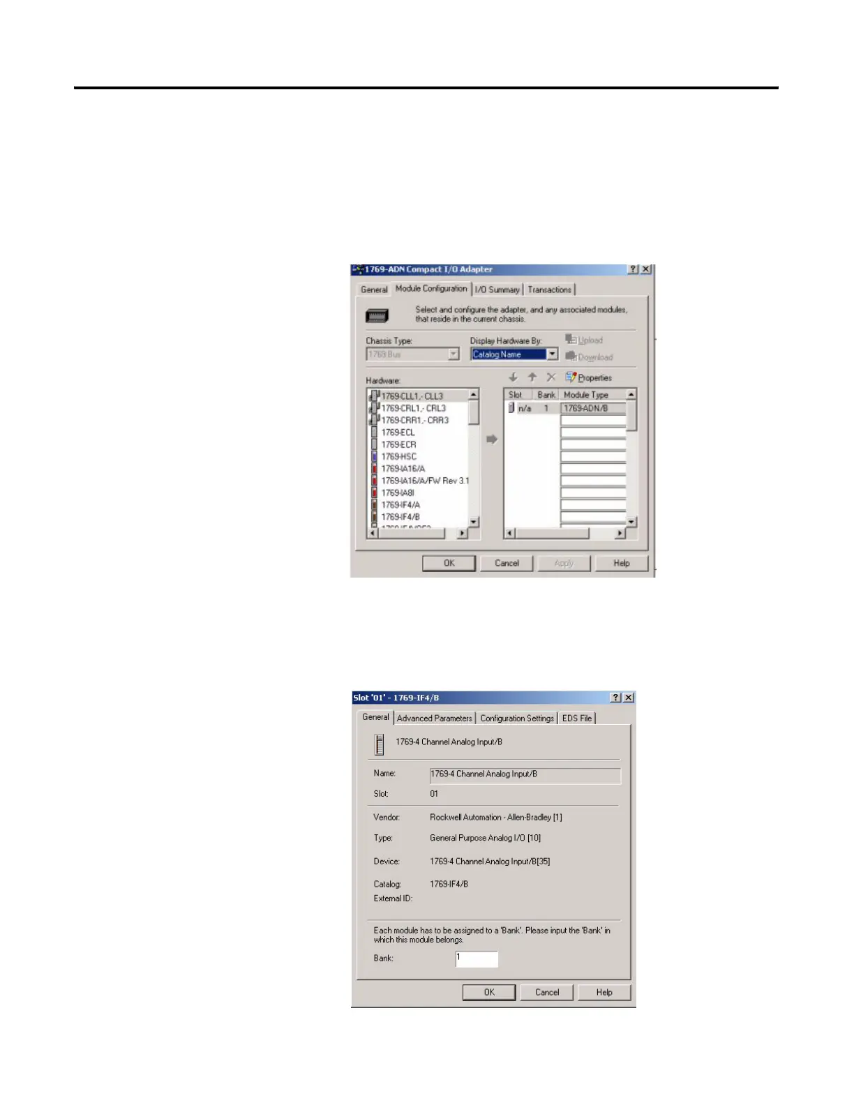
Configure the 1769-IF4 Input
Module Example
The 1769-ADN adapter appears in slot 0. Your I/O modules, power supplies,
end caps, and interconnect cables must be entered in the proper order,
following the 1769 I/O rules contained in the DeviceNet Adapter User
Manual, publication 1769-UM001A. To simplify this example, we placed the
1769-IF4 in slot 1 to show how it is configured.
1. To place the input module into slot 1, click Module Configuration.
A list of all possible 1769 products appears.
2. Select the 1769-IF4/B.
Slot 1 appears to the right of the 1769-IF4.
3. Under the General tab, select the appropriate bank.
Bank 1 was selected in this example.
 Loading...


