Publication 1769-UM002B-EN-P - July 2005
Overview 1-5
General Diagnostic Features
The analog modules contain diagnostic features that can help you identify the
source of problems that may occur during power-up or during normal channel
operation. These power-up and channel diagnostics are explained in chapter 6,
Module Diagnostics and Troubleshooting.
System Overview
The modules communicate to the controller through the bus interface. The
modules also receive 5 and 24V dc power through the bus interface. The
1769-IF4, -OF2, -OF8C, and -OF8V modules feature an external 24V dc
power switch, providing you with the option of using an external power
supply. See External Power Switch on page 2-10 for details.
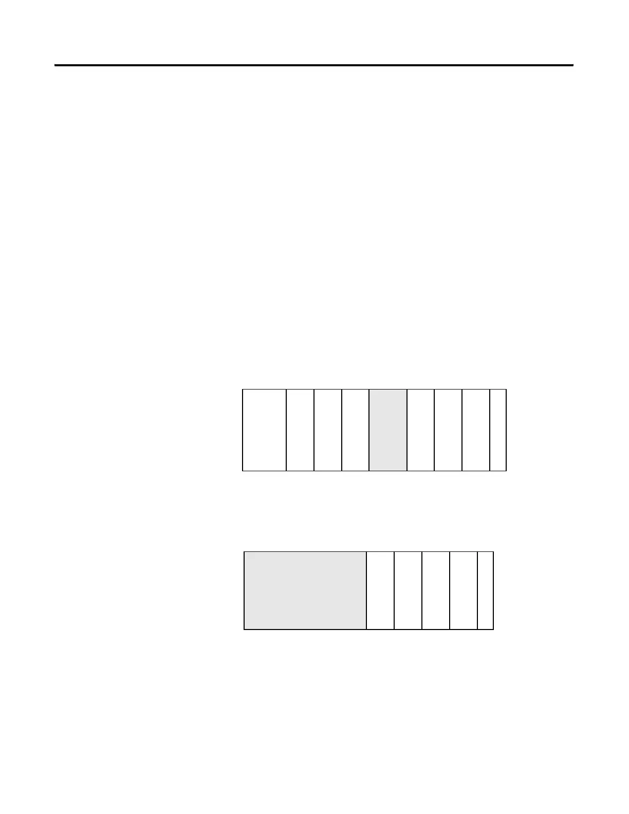
You can install as many analog modules as your power supply can support.
However, the modules have a power supply distance rating of 8, which means
that they may not be located more than 8 modules away from the system
power supply.
Figure 1.4 Determine Power Supply Distance
1
1123432
234
System Power Supply
Compact I/O
Compact I/O
Compact I/O
End Cap
CompactLogix Controller
or I/O Communication
Adapter
Compact I/O
Compact I/O
Compact I/O
OR
Power Supply Distance
Compact I/O
Compact I/O
Compact I/O
Compact I/O
End Cap
MicroLogix 1500 Controller
with Integrated System
Power Supply
Power Supply Distance

 Loading...


