Publication 1769-UM002B-EN-P - July 2005
Module Data, Status, and Channel Configuration for the Output Modules 4-25
1769-OF8C and -OF8V Enable/Disable Channel
This configuration selection (bit 15) allows each channel to be individually
enabled.
Clamping/Limiting
Clamping limits the output from the analog module to remain within a range
configured by the controller, even when the controller commands an output
outside that range. This safety feature sets a high clamp and a low clamp.
Once clamps are determined for a module, any data received from the
controller that exceeds those clamps sets an appropriate limit alarm and
transitions the output to that limit but not beyond the requested value.
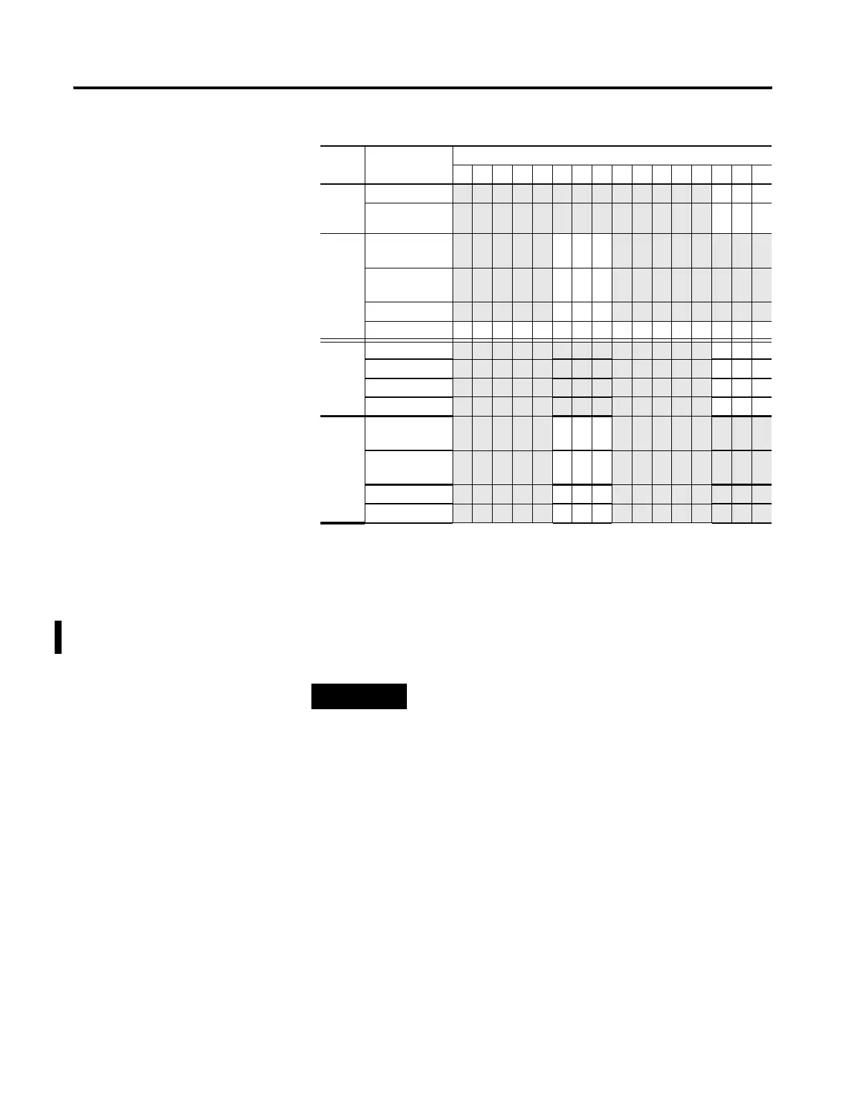
Table 4.13 1769-OF8C and -OF8V Output Channel Configuration
Define Indicate this These bit settings
1514131211109876543210
1769-OF8C
Output
Range
Select
0 to 20 mA dc 000
4 to 20 mA dc
001
Output
Data
Select
Raw/Proportion
al Counts
0 0 0
Engineering
Units
001
Scaled for PID 010
Percent Range 0 1 1
1769-OF8V
Output
Range
Select
-10…+10V dc 000
0…5V dc
001
0…10V dc
010
1…5V dc
011
Output
Data
Select
Raw/Proportion
al Counts
000
Engineering
Units
001
Scaled for PID 010
Percent Range 011
TIP
A channel that is not enabled has zero voltage or current at
its terminal.

 Loading...


